
N-way, ridged waveguide, radial power combiner/divider

a technology of radial power combiner and divider, which is applied in the direction of waveguide type devices, coupling devices, basic electric elements, etc., can solve the problems of limiting the power handling capability of the device versus the waveguide architecture, wilkinson power combiner/divider is highly frequency-dependent for isolation, and the insertion loss of the waveguide is low, and the effect of minimizing the effect of a failed modul

Active Publication Date: 2017-11-23
COBHAM ADVANCED ELECTRONICS SOLUTIONS
View PDF5 Cites 12 Cited by
  • Summary
  • Abstract
  • Description
  • Claims
  • Application Information

AI Technical Summary

Benefits of technology

The patent text describes a new type of power combiner / divider called an NRRPCD that has many benefits for certain applications. It has very low signal loss because of the design of the waveguide, which is made up of ridges that separate the signals and reduce interference. This design also ensures that if one part fails, the output of the device will not be affected. The NRRPCD's symmetrical shape also allows for good balance between different ports and ensures that signals are in the correct phase to each other. The text emphasizes that the phase match is not affected by the number of ports on the device, meaning that even if there are more ports, the device will still work properly.

Problems solved by technology

The Wilkinson power combiner / divider is typically limited in how much power it can handle and dissipate.
Its isolation resistors and the mode of propagation limit the power handling capability of the device versus waveguide architecture.
Additionally, the Wilkinson power combiner / divider is highly frequency-dependent for isolation.
Because of this, additional quarter-wave sections and resistors may be added to increase the bandwidth, which may result in higher loss, increase in package size, and potentially lower power handling capabilities with added costs.
These technologies have comparatively higher insertion loss as compared to a ridged waveguide radial power combiner / divider.
Furthermore, stripline, microstrip, slabline and suspended substrate stripline typically do not have the peak or average power handling characteristics of a ridged waveguide structure, thus significantly reducing the ability to produce high enough power to replace existing high power vacuum tube amplifiers.
This, in return, produces the potential for a considerable tolerance stack up that degrades the phase match across each port.
The phase match of the network becomes more complicated as the number of ports increase; in other words, as the number of ports increase in a branching transmission line, the branching network gets larger, which increases how much the phasing will deviate between ports due to slight geometric changes in the branching structure and quarter wave transforms.
Signals that are out of phase are prone to cancel each other out, multiply the signal, or decrease the signal strength.
Depending on how broadband the combiner / divider is, a change in frequency could create inconsistent energy transfer.
The decrease in signal strength reduces the efficiency of the amplifying network.
However, where a free-emitting radial power combiner lacks in cross-port isolation, it has a significant improvement in cross port phase matching and insertion loss performance, which is also not limited by the quantity of ports.

Method used


Image

  • N-way, ridged waveguide, radial power combiner/divider
  • N-way, ridged waveguide, radial power combiner/divider
  • N-way, ridged waveguide, radial power combiner/divider

Examples


example 1

-Band, NRRPCD

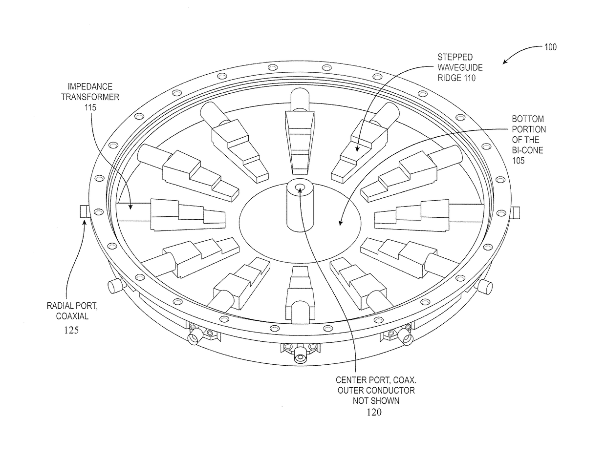
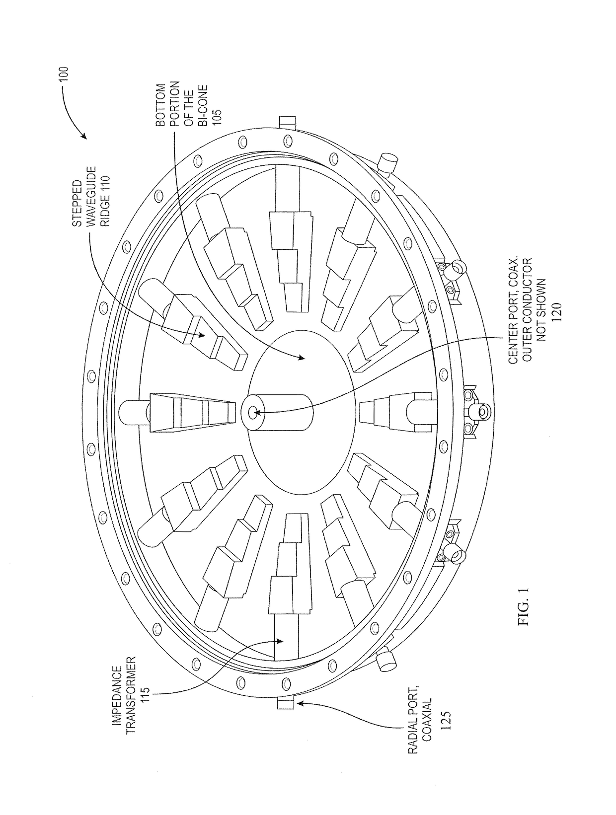
[0029]Referring to FIG. 1 is an example of an internal view of a solid model for a 12-Way NRRPCD 100, according to an embodiment. The figure shows the 12-Way design 100 without the cover, exposing the symmetrically-patterned radial combining / dividing structures and the bi-conical center port 105. The cross section in FIG. 1 shows a bi-conical center port 105, multiple end-launch waveguide launches 110 coupled to the bi-conical center port 105, and multiple impedance transformers 115 correspondingly coupled to the multiple end-launch waveguide launches 110. Coupled to the impedance transformers 115 are corresponding radial ports 125.

[0030]The 12-Way design 100 has a single step cylinder impedance transform and a stepped waveguide end-launch ridge. The bi-conical center port 105 may include an impedance transformer, and may be encased in a dielectric 120. The dielectric can also be used to electrically tune the structure's resonant cavity.

[0031]According to an embodiment ...

example 2

-Band, NRRPCD

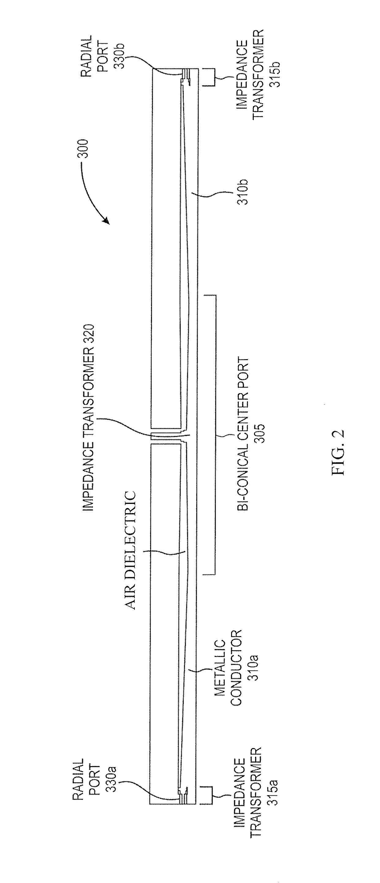
[0034]Referring to FIG. 2 is a cross-sectional view of a 68-Way, X-Band, NRRPCD 300, according to an embodiment. The cross-section shows a bi-conical center port 305, left and right end-launch waveguide launches 310a,b coupled to the bi-conical center port 305, and left and right impedance transformers 315a,b correspondingly coupled to the multiple end-launch waveguide launches 310a,b. The bi-conical center port 305 may include an impedance transformer 320, and may be encased in a fluorocarbon dielectric. Coupled to the impedance transformers 315a,b are corresponding radial ports 330a,b. While the cross section of FIG. 2 shows only two waveguide end-launches 310a,b, two impedance transformers 315a,b, and two radial ports 330a,b, it should be understood that the particular 68-Way design 300 has 68 such waveguide end-launches, impedance transformers, and radial ports.

[0035]Referring to FIG. 3 is an internal view of the 68-Way NRRPCD 300 of FIG. 2, according to an embodime...

example 3

-Band, NRRPCD

[0037]Referring to FIG. 4 is an internal view of a RF simulation model of an example of a 75-Way, S-Band, NRRPCD 800, according to an embodiment. A single stepped ridge and half of the bi-conical center port are shown. FIG. 4 shows a bi-conical center port 805, an end-launch waveguide 810 coupled to the bi-conical center port 805, and an impedance transformer 815 coupled to the end-launch waveguide 810. The bi-conical center port 805 may include an impedance transformer 820, and may be encased in a dielectric 825. Coupled to the impedance transformer 815 is a radial port 830.

[0038]The example 75-Way design 800 uses a stepped ridge structure that resembles the 12-Way design 100. The impedance transform 815 on the radial port 830 uses a conical frustum that launches into the tapered stepped ridge 810. The bi-conical center port 805 is encased in a fluorocarbon dielectric 825 to increase the peak and average handling power. The fluorocarbon 825 can be used as a heat transf...


PUM


Abstract

A microwave radial power divider / combiner device in which ridged waveguides structures are provided to provide adjacent-port isolation, large bandwidth, consistent cross-port phase matching, low insertion loss, and high peak and average power handling characteristics. The device includes a single rectangular input / output waveguide coupled to a bi-conical waveguide, which in turn is coupled to multiple ridged waveguides. These ridged radial waveguides are coupled to waveguide end-launches and impedance transformers located around the circumference of the device.

Description

FIELD OF THE INVENTION[0001]The present disclosure is directed generally to an N-way, ridged waveguide, radial power combiner / divider that minimizes loss while maintaining a matched condition on all ports.BACKGROUND[0002]A dual-purpose power combiner / divider is required for a solid state power amplifier design. Current technology for solid state combiner / divider designs uses microstrip, stripline, slabline, suspended substrate stripline, or waveguide designs. For example, Wilkinson power splitters, rat race, quadrature 90-degree hybrid, and reactive-tee are all types of splitters, combiners, and dividers that use microstrip, stripline, slabline, and suspended substrate stripline designs. Free-emitting conical radial power combiners and magic-tees use waveguide technology. Both the Wilkinson and wired radial power combiners / dividers are a form of a branching transmission line network, also called a corporate feed network.[0003]The Wilkinson power combiner / divider is typically limited...

Claims


Application Information

Patent Timeline
Patent Type & Authority Applications(United States)
IPC IPC(8): H01P5/16
CPCH01P5/16
Inventor DANDERSON, BRETT
Owner COBHAM ADVANCED ELECTRONICS SOLUTIONS
Learn More