Light source module

a technology of light source module and light source, applied in the field of light source module, can solve the problems of artificial light source that cannot serve as ideal light source for improving the growth rate of plants, overheating plants, and the failure of plants to achieve the best growth condition of plants, etc., and achieve the effect of increasing the growth rate of aquatic organisms

Active Publication Date: 2017-11-30
NATIONAL CHUNG CHENG UNIV +1
View PDF9 Cites 6 Cited by
  • Summary
  • Abstract
  • Description
  • Claims
  • Application Information

AI Technical Summary

Benefits of technology

[0006]The object of the present invention is to provide a light source module, which may simulate the spectrum of sunlight underwater with low heat radiation. The light source module of the present invention may be utilized to cultivate aquatic organisms for increasing the growing rate of those aquatic organisms.
[0008]Accordingly, the light emitting units with different wavelengths in the LED array may be mixed and combined to provide the light needed for the aquatic organisms. Since the light source provided by the light source module is luminescence, the problems of rising temperature of the environment of those aquatic organisms due to the artificial light may be prevented. For example, when the light source module is utilized as a grow light for cultivating the water aquatic plants, the problems of overheated plants caused by the heat radiation may be prevented, thus the cost for lowering the temperature may be decreased and the close illumination may be achieved. In addition, the LED array of the present invention may be driven in various ways through the circuit design, accordingly, the light emitting units of the LED array may be driven to match the spectrum of the sunlight, and alternatively, specific light emitting units of the LED array may be driven to give the desired light module such as blue light mode to make the coral fluorescent more apparent, or reinforce the red light to make the red coral more significant.
[0009]In the present invention, the LED array may be arranged in a N×M array (N and M are positive integer, N≧3, M≧2) and light emitting units with different wavelength preferably be arranged in the mosaic mode to evenly mix the light. For example, the four adjacent light emitting units preferably provide at least two emission peaks with different peak wavelength (λmax) to form a partial 2×2 sub-array of mixed light, thus the light mixing effect of the LED array may be improved based on a plurality of the partial sub-array of mixed light. However, the arrangement of the LED array is not limited to the aforementioned mosaic mode and the LED array can be arranged in the straight mode (that is, the light emitting units having the same wavelength may be arranged adjacently in longitudinal or transverse direction) or other arrangements.
[0013]In addition, the present invention further provides a use of the aforementioned light source module, which can be used to provide the light source for cultivating aquatic organisms and increase the growing rate of the aquatic organisms.

Problems solved by technology

Accordingly, the organisms grew by artificial cultivation usually fail to achieve their best growth condition due to the light source.
The conventional artificial light sources for the plant cultivation mainly include incandescent lamp, daylight lamp, halogen lamp, high-pressure sodium lamp, fluorescent lamp, or the like, however, the spectrum of the lights emitted by those artificial light sources do not match with the spectrums of natural lights of their natural living environments, and even some of the artificial light sources may generate heat radiation which causes overheated plants.
Therefore, those artificial light sources cannot serve as ideal light sources to improve the growing rate of plants.
Therefore, the current light source simulating the sunlight cannot provide the light source with the best light condition that needed by aquatic organisms.

Method used


Image

  • Light source module
  • Light source module
  • Light source module

Examples


embodiment 1

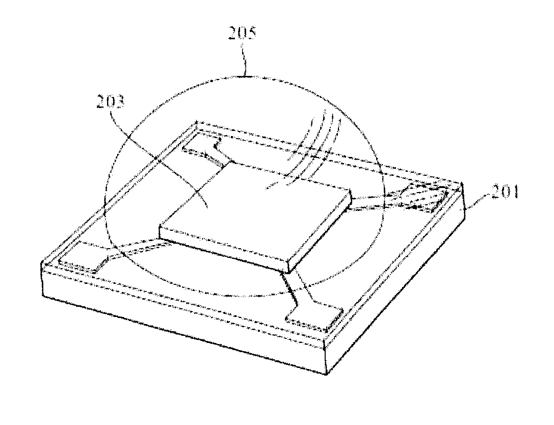
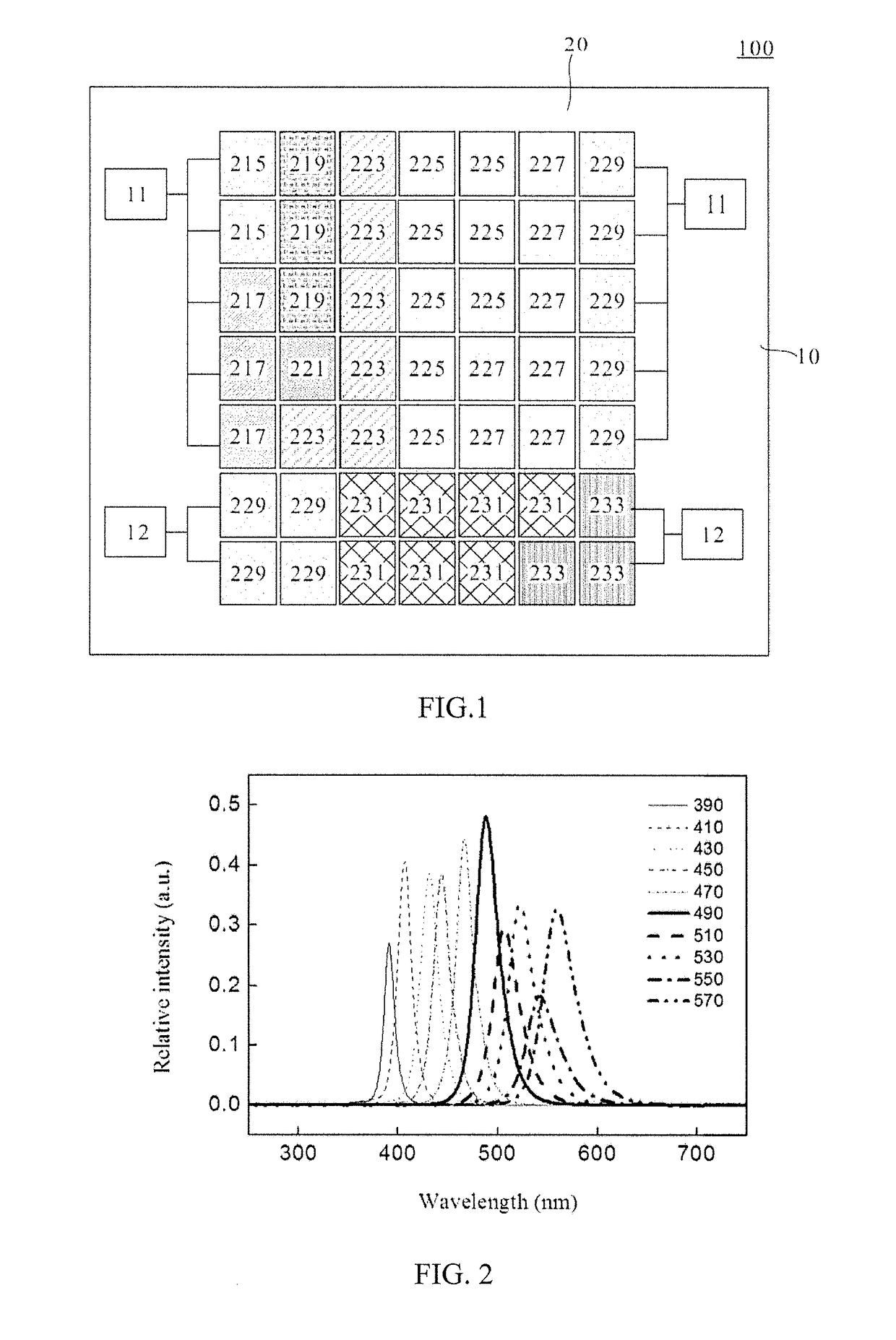
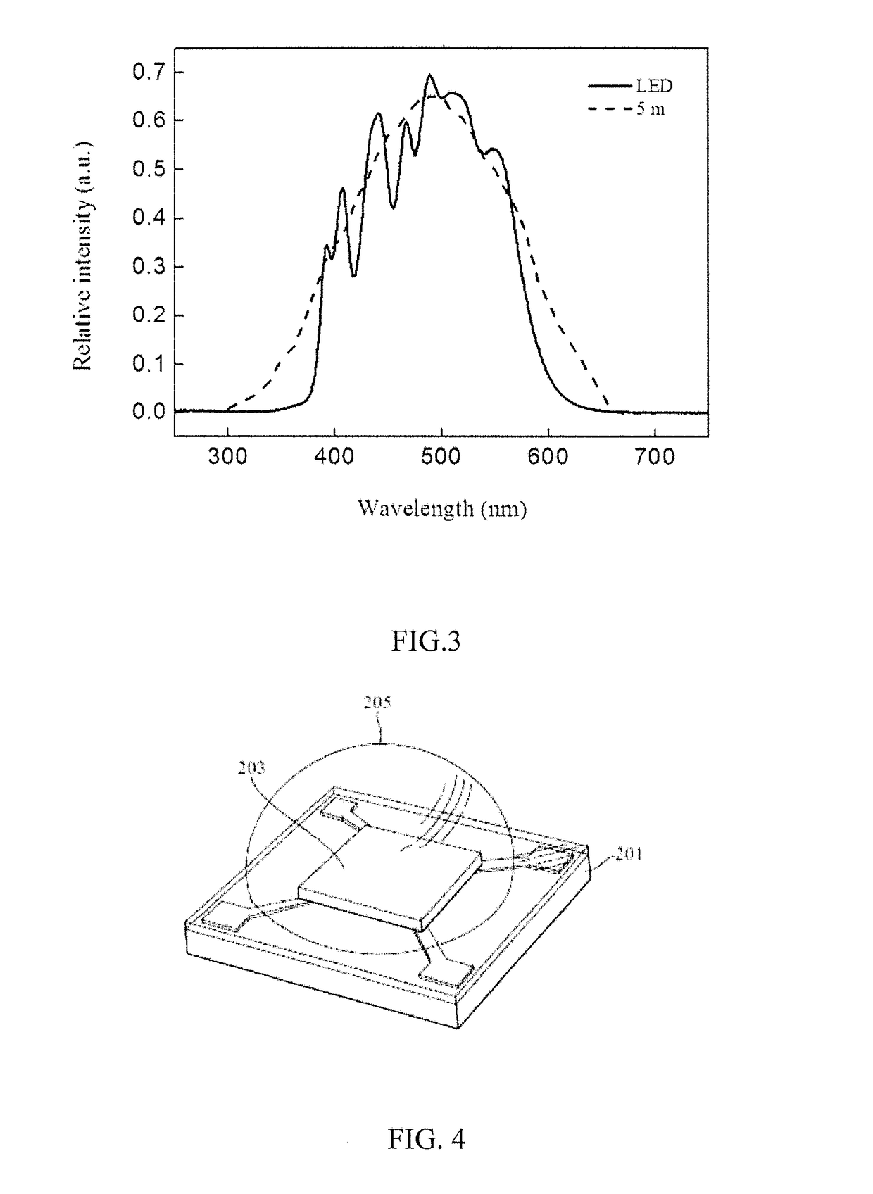
[0063]Please refer to FIG. 1, which illustrates the light source module 100 of one embodiment of the present invention. As illustrated in FIG. 1, the light source module 100 of the present invention comprises a wiring board 10 and a LED array 20, wherein the LED array is configured with multi-wavelength LED elements and electrically connects to the electrodes 11, 12 of the wiring board 10. Accordingly, those multi-wavelength LED elements are utilized to simulate the spectrum of sunlight underwater. The following description exemplifies the simulation of the spectrum of sunlight 5, 10, 15, and 20 meters underwater.

[0064]First, the simulation of the spectrum of sunlight 5 meters underwater is exemplified. As illustrated in FIG. 1, two 390 nm LED elements 215, three 410 nm LED elements 217, three 430 nm LED elements 219, one 450 nm LED element 221, six 470 nm LED elements 223, eight 490 nm LED elements 225, seven 510 nm LED elements 227, nine 530 nm LED elements 229, seven 550 nm LED e...

embodiment 2

[0072]Please refer to FIG. 14, which illustrates the LED array 20 of another embodiment of the present invention. The present embodiment utilized 100 light emitting elements to simulate the spectrum of sunlight 5, 10, 15, and 20 meters underwater.

[0073]First, the simulation of the spectrum of sunlight 5 meters under water is exemplified. As illustrated in FIG. 14, three 350 nm LED elements 211, three 370 nm LED elements 213, two 390 nm LED elements 215, three 410 nm LED elements 217, four 430 nm LED elements 219, one 450 nm LED element 221, six 470 nm LED elements 223, eleven 490 nm LED elements 225, six 510 nm LED elements 227, twelve 530 nm LED elements 229, eight 550 nm LED elements 231, eighteen 570 nm LED elements 233, ten 590 nm LED elements 235 were applied in the present embodiment, wherein the lights with multi-wavelength that emitted from the LED chips directly. 10×10 LED array 20 was accomplished matching those LED elements and thirteen white light LED elements 251. Herei...

embodiment 3

[0084]The present embodiment utilized 10×10 LED array similar to the aforementioned embodiment 2 to mix and match the spectrum, but the LED array of the present embodiment further provided a fourth group of emission peaks. The simulation of the spectrum of sunlight 5 meters underwater is exemplified. As illustrated in FIG. 45, three 350 nm LED elements 211, three 370 nm LED elements 213, two 390 nm LED elements 215, three 410 nm LED elements 217, three 430 nm LED elements 219, three 450 nm LED elements 221, six 470 nm LED elements 223, ten 490 nm LED elements 225, six 510 nm LED elements 227, fourteen 530 nm LED elements 229, seven 550 nm LED elements 231, twenty-five 570 nm LED elements 233, twelve 590 nm LED elements 235, one 610 nm LED element 241, one 630 nm LED element 243, and one 650 nm LED element 245 were applied in the present embodiment, wherein the lights with multi-wavelength were emitted from the LED chips directly. Similarly, the present embodiment is not limited to t...


PUM


Abstract

A light source module includes a wiring board and a LED array electrically connected to the wiring board. The LED array can be driven to emit a first group of emission peaks in 300 nm≦λmax<450 nm, a second group of emission peaks in 450 nm≦λmax<550 nm, and a third group of emission peaks in 550 nm for matching the spectrum of sunlight underwater. When the maximum peak intensity of the emission peaks in the second group is taken as 1.0, the peak intensity Ia of each emission peak in the first group is in a range of 0<Ia≦0.9, and the peak intensity Ib of each emission peak in the third group is in a range of 0<Ib≦0.9. Accordingly, the light source module is suitable for aquatic species and can enhance growing rate of the aquatic species.

Description

CROSS REFERENCE TO RELATED APPLICATION[0001]This application claims the benefits of the Taiwan Patent Application Serial Number 105116261, filed on May 25, 2016, the subject matter of which is incorporated herein by reference.BACKGROUND OF THE INVENTION1. Field of the Invention[0002]The present invention relates to a light source module, particularly, to a light source module simulating the spectrum of sunlight underwater.2. Description of Related Art[0003]In nature, sunlight serves as the main light source of the environment for the living organisms. The sunlight received at different geographical environments and latitudes may have different spectrum, therefore, the organism species vary at the different regions. However, the natural light received by the organisms in the artificial nurturing environment differs from that in the natural environment. Accordingly, the organisms grew by artificial cultivation usually fail to achieve their best growth condition due to the light source...

Claims


Application Information

Patent Timeline
Patent Type & Authority Applications(United States)
IPC IPC(8): F21K9/64H01L33/62H01L33/54H01L33/48F21S10/00F21V19/00H05B33/08H01L33/50H05B44/00
CPCF21Y2113/13F21K9/64F21V19/0025F21S10/00F21Y2115/10H01L33/486H01L33/62H01L33/502H01L33/54H05B33/0845F21V9/30A01G7/045F21S8/00A01G33/00A01H3/02C12M31/10C12M41/06Y02P60/14H05B45/10
Inventor TING, CHU-CHIHUANG, YU-WEN
Owner NATIONAL CHUNG CHENG UNIV
Why Eureka
Try Eureka