Flow channel device
- Summary
- Abstract
- Description
- Claims
- Application Information
AI Technical Summary
Benefits of technology
Problems solved by technology
Method used
Image
Examples
first embodiment
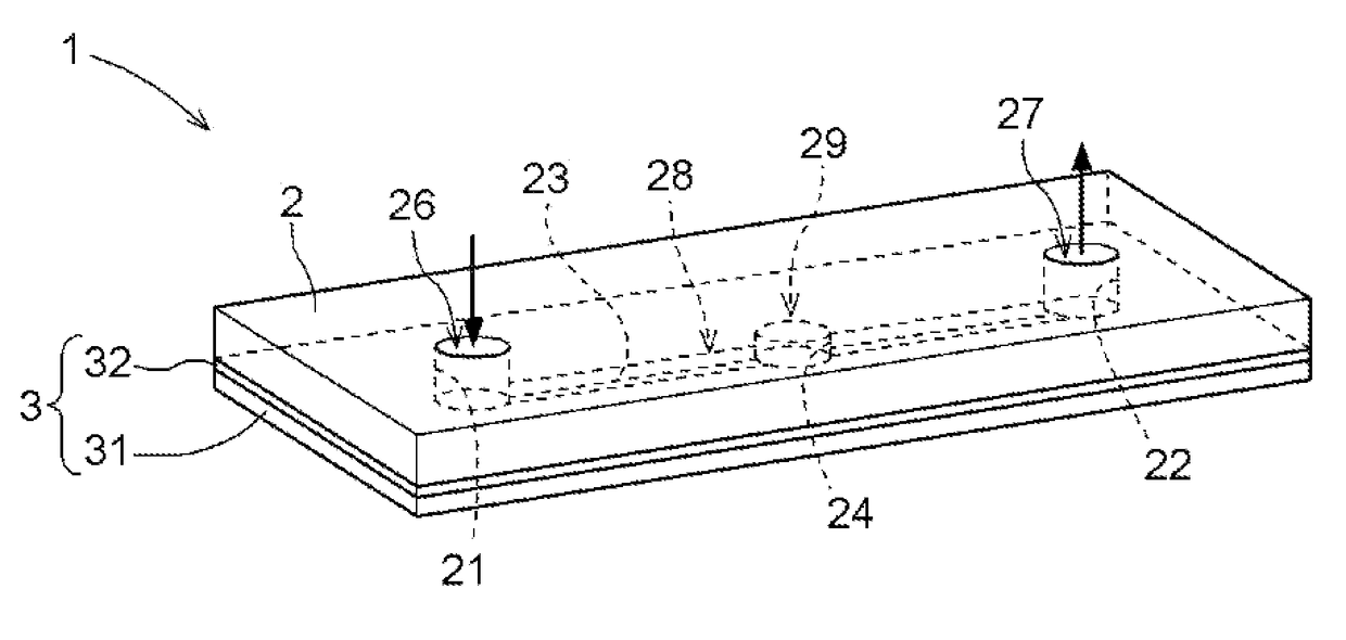
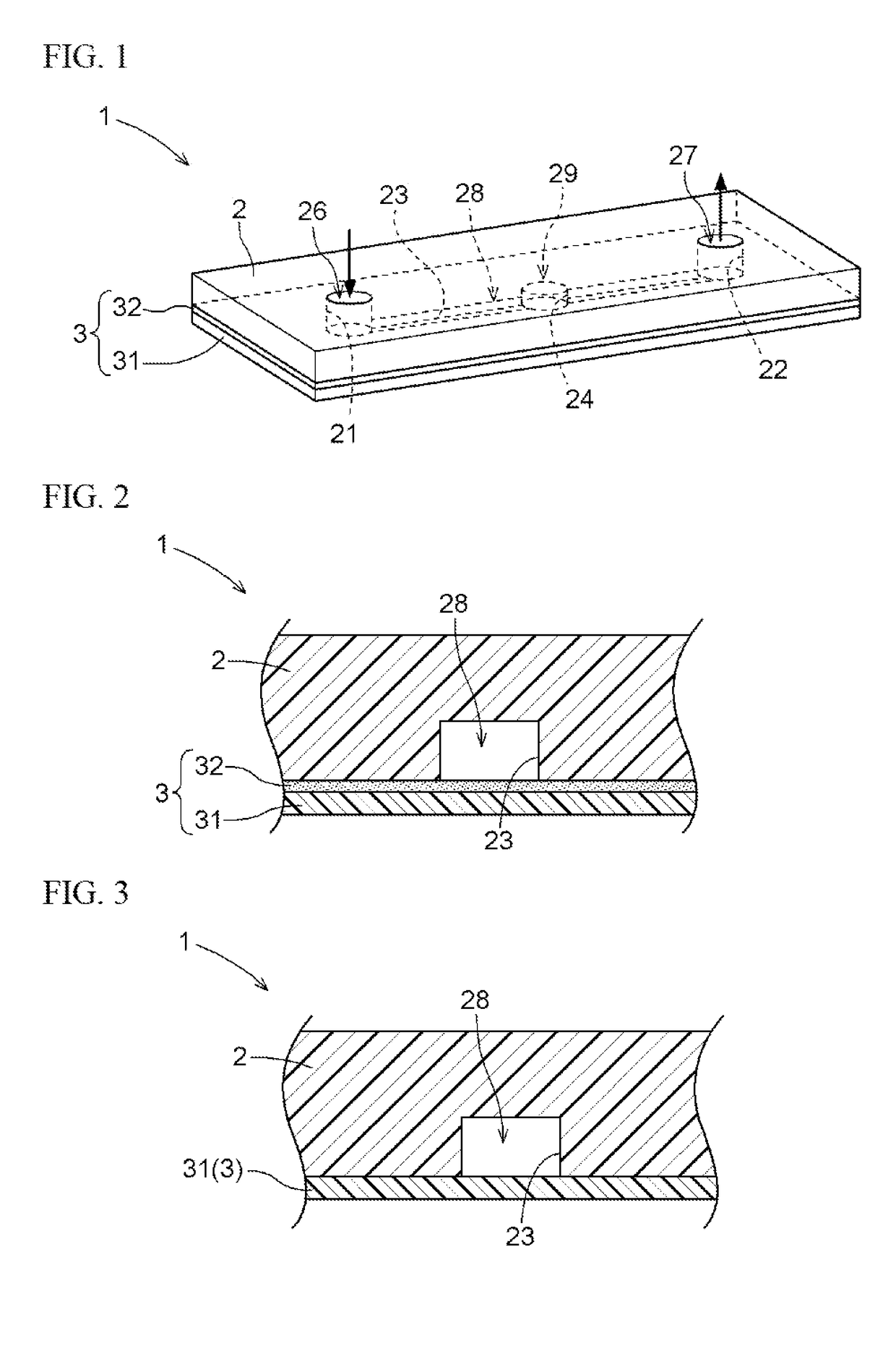
[0027]An embodiment of a flow channel device of the present invention will be described with reference to drawings. As shown in FIGS. 1 and 2, a flow channel device 1 includes a base material 2 having a groove 23 and a coating material 3 which is integrated with the base material 2 so as to cover the groove 23. A flow channel 28 is formed between the base material 2 and the coating material 3. The flow channel 28 is divided and formed by the inner surface of the groove 23 in the base material 2 and the inner surface of a portion facing to the groove 23 in the coating material 3.
[0028]The base material 2 is formed, for example, into a plate shape with several cm square having a thickness of about 1 mm to 5 mm. In the present embodiment, a first through-hole 21, a second through-hole 22, the groove 23, and a concavity 24 are formed in the base material 2. The first through-hole 21 and the second through-hole 22 are formed so as to penetrate through the base material 2 in a thickness d...
second embodiment
[0061]As shown in FIG. 3, a coating material 3 integrated with a base material 2 may be a fluid-impermeable film material 31 of a single layer. That is, the coating material 3 may be consisting of only the film material 31. In this second embodiment, a flow channel device 1 is constituted such that the base material 2 and the film material 31 are directly integrated without interposing an adhesive layer 32, unlike the above-described first embodiment.
[0062]The thickness of the film material 31 or a resin composition for forming a film material for producing the film material 31 may be the same as that in the coating material 3 of the first embodiment. In a case where the coating material 3 consists of the film material 31 of a single layer and the base material 2 and the film material 31 are directly integrated as in the present embodiment, it is preferable that the resin composition for forming a film material is the same as a resin composition for forming a base material or the ty...
example 1
[0085]A flow channel device 1 was produced according to the following procedure. First, an acrylic substrate having a size of 50 mm×50 mm×1.5 mm in thickness was produced using an acrylic resin (DELPET 70NH manufactured by Asahi Kasei Corporation) and a plurality of grooves 23 having a width of 100 μm and a depth of 30 μm were formed using a cutting machine to use this substrate as a base material 2. Pure water was added dropwise to this base material 2 and the contact angle was measured using an automatic contact angle meter (product number: CA-V series manufactured by Kyowa Interface Science Co., LTD.). The measured contact angle was 70°.
[0086]Next, an acrylic film was obtained such that a resin containing 99.0 parts by weight of methyl methacrylate and 1.0 part by weight of butyl acrylate was molded into a film form having a thickness of 125 μm.
[0087]A principal surface of this acrylic film was coated with an adhesive (6LQ-002 manufactured by TAISEI FINE CHEMICAL CO., LTD.) and t...
PUM
| Property | Measurement | Unit |
|---|---|---|
| Angle | aaaaa | aaaaa |
| Angle | aaaaa | aaaaa |
| Adhesivity | aaaaa | aaaaa |
Abstract
Description
Claims
Application Information
 - R&D
- Intellectual Property
- Life Sciences
- Materials
- Tech Scout
- Unparalleled Data Quality
- Higher Quality Content
- 60% Fewer Hallucinations
Browse by: Latest US Patents, China's latest patents, Technical Efficacy Thesaurus, Application Domain, Technology Topic, Popular Technical Reports.
© 2025 PatSnap. All rights reserved.Legal|Privacy policy|Modern Slavery Act Transparency Statement|Sitemap|About US| Contact US: help@patsnap.com


