Energy Recovery System

a technology of energy recovery and energy storage, which is applied in the direction of domestic hot water supply systems, lighting and heating apparatus, heating types, etc., can solve the problems of unit maintenance and ongoing challenges, waste of heat generated by combustion within the engine, etc., and achieve optimal thermodynamic efficiency, maximize heat recovery and reclaimed heat applications, and efficient packaging

a technology of energy recovery and energy storage, which is applied in the direction of domestic hot water supply systems, lighting and heating apparatus, heating types, etc., can solve the problems of unit maintenance and ongoing challenges, waste of heat generated by combustion within the engine, etc., and achieve optimal thermodynamic efficiency, maximize heat recovery and reclaimed heat applications, and efficient packaging

US20170356310A1Active Publication Date: 2017-12-14ENGINUITY POWER SYST INC

Image

  • Energy Recovery System
  • Energy Recovery System
  • Energy Recovery System

Examples


Embodiment Construction

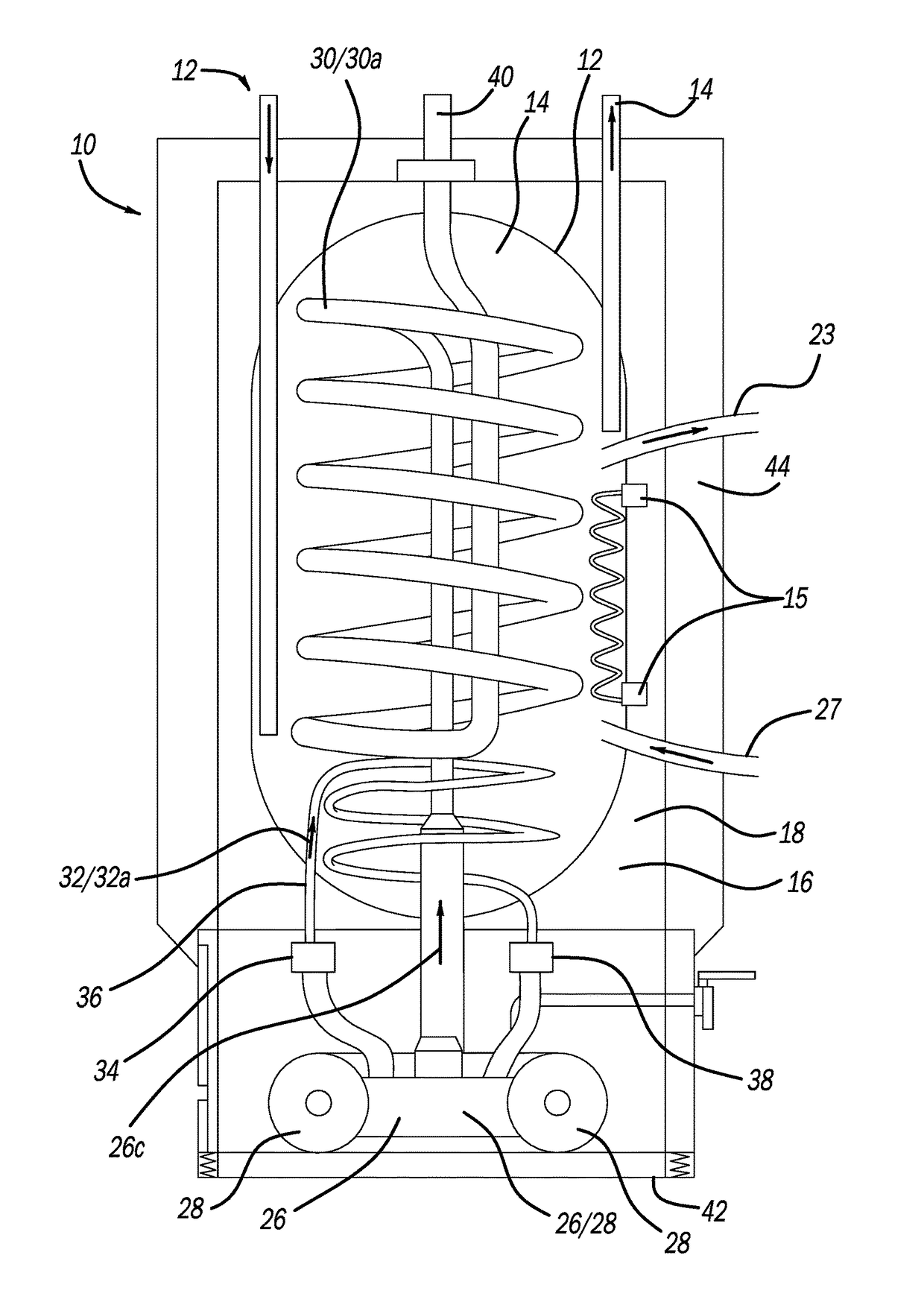
[0030]The present invention utilizes an opposed-piston engine to provide energy from the thermo-dynamic transfer of heat energy created during the operation of the four-stroke opposed piston engine. Although not necessarily so limited, a preferred engine is a four-stroke opposed piston engine that utilizes a fuel other than diesel. Other fuels include gasoline, propane, or natural gas, for example. Certain efficiencies are realized with the use of an opposed-piston configuration, particularly when a four-stroke engine is employed. It has been found that packaging efficiencies are improved thereby resulting in a more-compact energy unit. Further, it has been found that a four-stroke opposed piston engine is compliant with pertinent environmental regulations of the EPA.

[0031]The present energy recovery system 10 includes an engine that produces heat in both the exhaust stream and in a coolant stream. A housing 20 contains a first pressure vessel 12 containing a first fluid or liquid 1...


PUM

PropertyMeasurementUnit
stroke lengthaaaaaaaaaa
thermodynamicaaaaaaaaaa
pressureaaaaaaaaaa

Abstract

A combined heat and power system, or an energy system, is provided. A four-stroke opposed-piston engine provides efficient power from a generator set or genset. A heat exchange system is provided within the energy system to provide efficient waste heat recovery as the engine is operated.

Description

CROSS-REFERENCE TO RELATED APPLICATIONS[0001]This application claims the benefit of U.S. Provisional Patent Application Ser. No. 62 / 349,346 filed on Jun. 13, 2016, and, this application also claims the benefit of U.S. Provisional Patent Application No. 62 / 419,188 having a filing date of Nov. 8, 2016, the teachings of both provisional applications herein incorporated by reference.TECHNICAL FIELD[0002]The present invention relates generally to a combined heat and power unit that stores, captures, and utilizes heat generated from an engine for a variety of applications, for example.BACKGROUND OF THE INVENTION[0003]A continuing challenge is to economically provide energy while yet reclaiming various aspects of the energy development such as heat. Yet another challenge is to reduce carbon emissions when operating combustion engines to produce energy such as electrical energy. Oftentimes, heat generated by combustion within the engine is wasted. Furthermore, challenges such as packaging a...

Claims


Application Information

Patent Timeline
14 Dec 2017
Publication
US20170356310A1
IPC
F01K23/10; H01M8/04014; F01N3/02; F01K23/08
CPC
F01K23/10; H01M8/04022; F01N3/02; F01K23/08; F01K23/065; F24D17/0005; F24D11/005; F24D17/001
Inventors
POWELL, GREGORY B.; WARREN, JAMES C.