Burner, combustor, and gas turbine

Active Publication Date: 2017-12-14
KAWASAKI HEAVY IND LTD
View PDF5 Cites 15 Cited by
  • Summary
  • Abstract
  • Description
  • Claims
  • Application Information

AI Technical Summary

Benefits of technology

[0024]This construction enables provision of a gas turbine equipped with a combustor capable of suppressing a NOx emission amount.
[0025]The present invention can provide the burner capable of suppressing a NOx emission amount by premixing the first fuel (

Problems solved by technology

Therefore, the hydrogen gas itself injected from the second fuel injection hole has a small penetrating force (i.e., a kinetic energy when the hydrogen gas is injected), so that stir

Method used


Image

  • Burner, combustor, and gas turbine
  • Burner, combustor, and gas turbine
  • Burner, combustor, and gas turbine

Examples


first embodiment

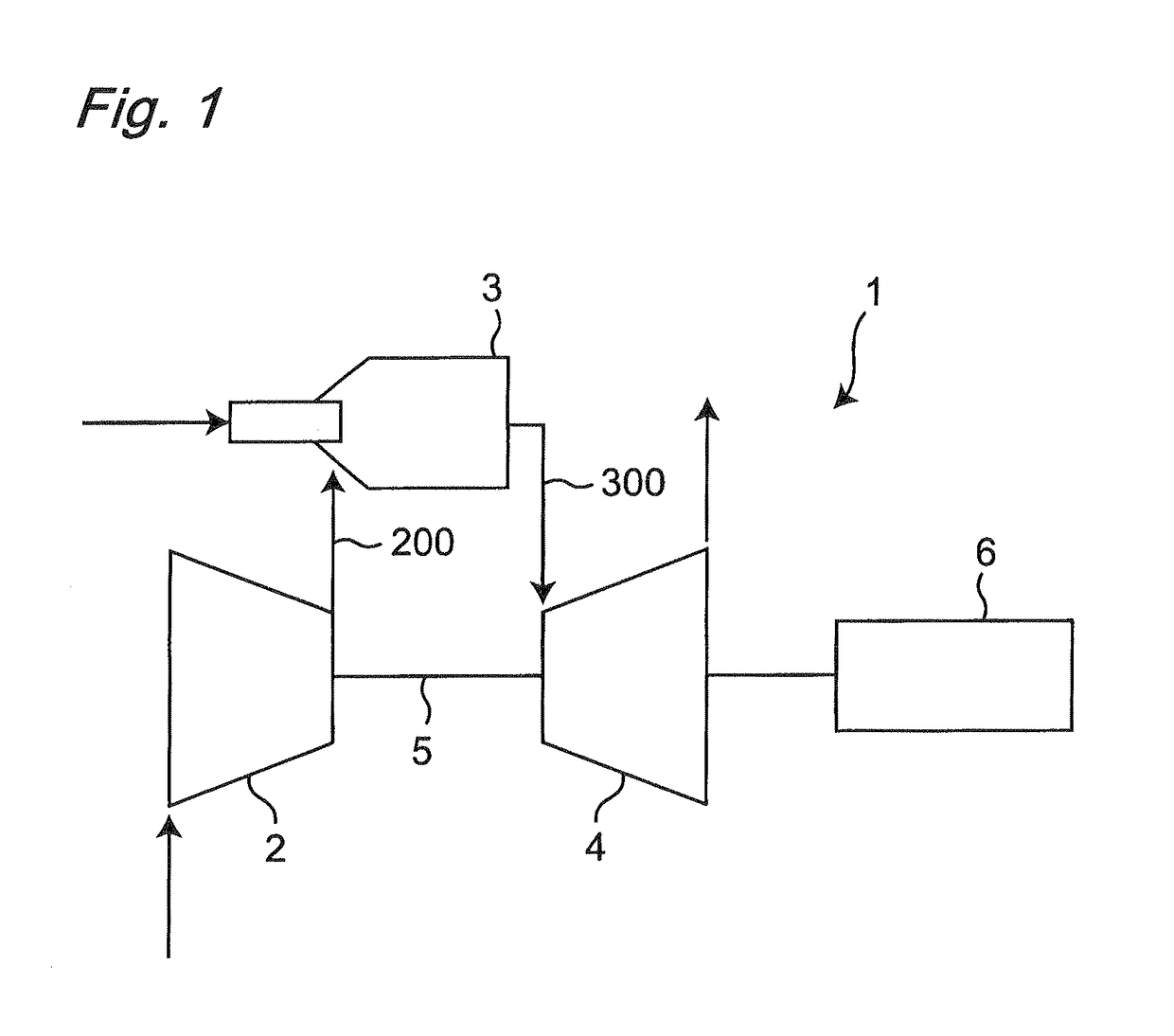
[0038]A general construction and function of a gas turbine is shown in FIG. 1. In the gas turbine 1, a compressor 2 sucks an atmospheric air to generate a compressed air 200. The compressed air 200 is combusted together with a fuel in a combustor 3 to generate a high-temperature high-pressure combustion product gas (hereinafter referred to as “combustion exhaust gas 300”). The combustion exhaust gas 300 is supplied to a turbine 4 and used for rotating a rotor 5. The rotation of the rotor 5 is transmitted to the compressor 2 and used for generating the compressed air 200 (hereinafter referred to as “combustion air 200”), while the rotation of the rotor 5 is transmitted to a generator 6 and used for electric generation, for example.

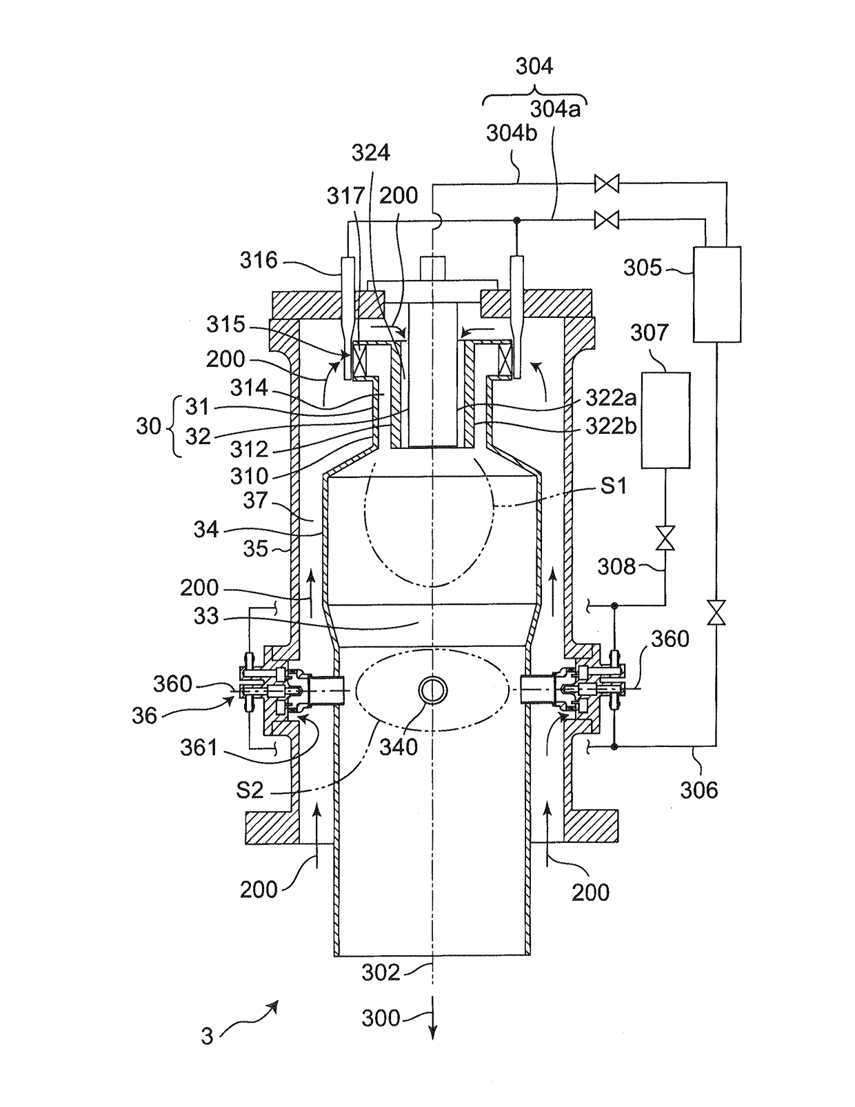
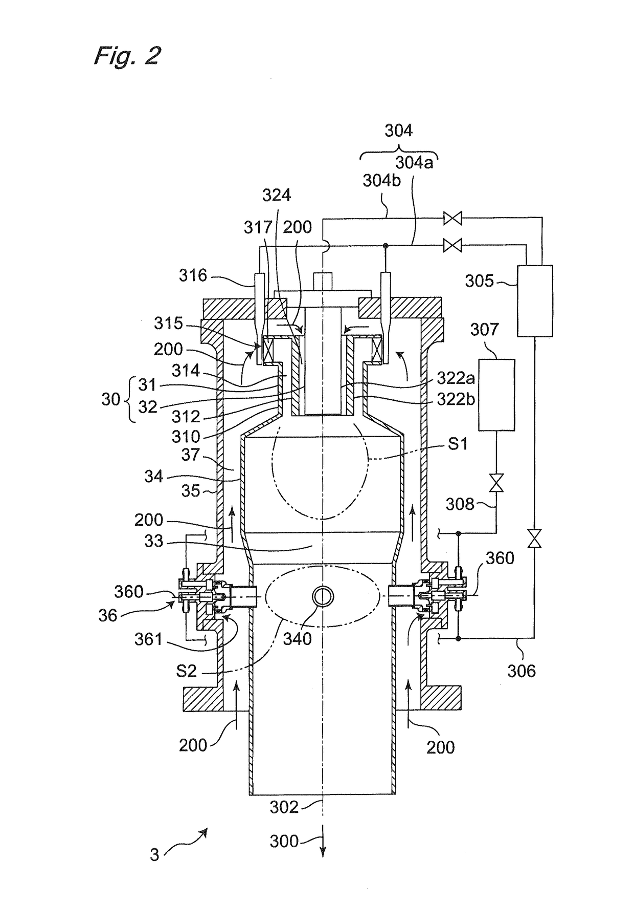
[0039]FIG. 2 shows the combustor 3. In this embodiment, the combustor 3 is a reverse-flow can-type combustor in which a flow direction of the compressed air 200 supplied from the compressor (see FIG. 1) (a direction from the top to the bottom of FIG. 1) and...

second embodiment

[0059]A reheating burner according to a second embodiment of the present invention will be described. FIG. 6 shows the reheating burner 36 according to the second embodiment of the present invention. The basic structure of the reheating burner 36 according to this embodiment is the same as the reheating burner 36 according to the first embodiment described with reference to FIG. 3 and, therefore, the same constituent portions are denoted by the same reference numerals and will not be described.

[0060]The reheating burner 36 according to this embodiment has two points different from the reheating burner 36 according to the first embodiment described with reference to FIG. 3 in that an inverted conical straightening protrusion part 390 extending in the premixing flow path 367 coaxially with the outer cylinder 364 is formed on the downstream-side wall surface of the head block 361 and that the first fuel introduction part 368 is configured to inject the natural gas from a plurality of f...

third embodiment

[0063]A reheating burner according to a third embodiment of the present invention will be described. FIGS. 7 to 10 show variations of the reheating burner 36 according to the third embodiment of the present invention. The structure of the reheating burner 36 of this embodiment is the same as the reheating burner 36 according to the first embodiment described with reference to FIG. 3 except that the burner has a second air introduction part 393 for introducing the combustion air 200 into the premixing flow path 367 on the downstream side relative to the first fuel introduction part 368 and, therefore, the same constituent portions are denoted by the same reference numerals and will not be described.

[0064]FIG. 7 shows a first example of the reheating burner according to the third embodiment of the present invention. The second air introduction part 393 of the first example is a gap formed between the first cylindrical part 362 (the first cylindrical body) and the second cylindrical pa...


PUM


Abstract

The present invention provides a burner, a combustor equipped with the burner, and a gas turbine, with which it is possible to premix a first hydrocarbon-based fuel (for example, natural gas), a second fuel (for example, hydrogen gas), and combustion air, and to spray into the combustion chamber of the combustor a thin and uniform concentration distribution of the premixed air, and with which it is possible to suppress the amount of NOx discharged. On the upstream side of the premix flow path, hydrogen gas is sprayed from second fuel spray nozzles, which project into the premix flow path, into the flow of the combustion air flowing toward the center from the outer edge of an outer cylinder, whereby a primary air-fuel mixture having a uniform concentration distribution is generated without affecting a low-speed region of the combustion air. Natural gas is then sprayed from first fuel spray nozzles into the primary air-fuel mixture, whereby the natural gas, which has a high specific gravity, and the primary air-fuel mixture are adequately mixed in a stirring fashion, and a secondary air-fuel mixture (premixed air) is generated that is lean and has a more uniform concentration distribution than the first air-fuel mixture. By combusting this type of premixed air in the combustion chamber, NOx in the combustion exhaust gas can be suppressed.

Description

TECHNICAL FIELD[0001]The present invention relates to a burner, a combustor, and a gas turbine.BACKGROUND[0002]In recent years, from the viewpoints of prevention of global warming and effective use of resources, gas turbines are requested to use a byproduct hydrogen gas secondarily generated from a manufacturing process of a petrochemical plant etc. in addition to a natural gas that is a main fuel of the gas turbines.[0003]Patent Document 1 discloses a gas turbine combustor having a combustion cylinder forming a combustion chamber thereinside, a casing covering the outside of the combustion cylinder and forming a flow path of a compressed air (hereinafter referred to as “combustion air”) supplied from a compressor around the combustion cylinder, a first fuel nozzle corresponding to a main burner disposed upstream of the combustion cylinder and injecting a first fuel (coal gasification gas) into the combustion chamber, and a plurality of second fuel nozzles corresponding to reheating...

Claims


Application Information

Patent Timeline
IPC IPC(8): F23R3/28F23C1/00F23D17/00F02C7/22F23R3/36F23C99/00
CPCF23R3/286F02C7/22F23C99/00F23D17/00F23R3/36F23C1/00F02C9/40F23R3/346F23R2900/00002F23R3/30F23R3/34F23R3/28
Inventor OGATA, MASAHIROODA, TAKEOKINOSHITA, YASUHIROHIRANO, KOHSHIUTO, TAKAHIRO
Owner KAWASAKI HEAVY IND LTD
Why Eureka
Try Eureka