SCR inlet flue gas pre-treatment system and method

A flue gas and inlet technology is applied in the field of pollutant control of layer-fired coal-fired boilers to achieve the effects of reducing escape, improving economy and simple system

Pending Publication Date: 2019-07-23
HARBIN INST OF TECH
View PDF8 Cites 6 Cited by
  • Summary
  • Abstract
  • Description
  • Claims
  • Application Information

AI Technical Summary

Problems solved by technology

[0011] The purpose of the present invention is to provide a kind of SCR inlet flue gas pretreatment system and method, adopt a kind of spraying urea solution at the furnace burnout chamber or spray ammonia solution before the inlet pipe of cyclone separator, and adopt the uniform flow un

Method used


Image

  • SCR inlet flue gas pre-treatment system and method
  • SCR inlet flue gas pre-treatment system and method
  • SCR inlet flue gas pre-treatment system and method

Examples


specific Embodiment approach 1

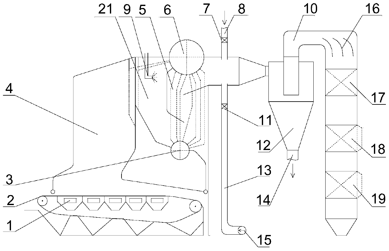
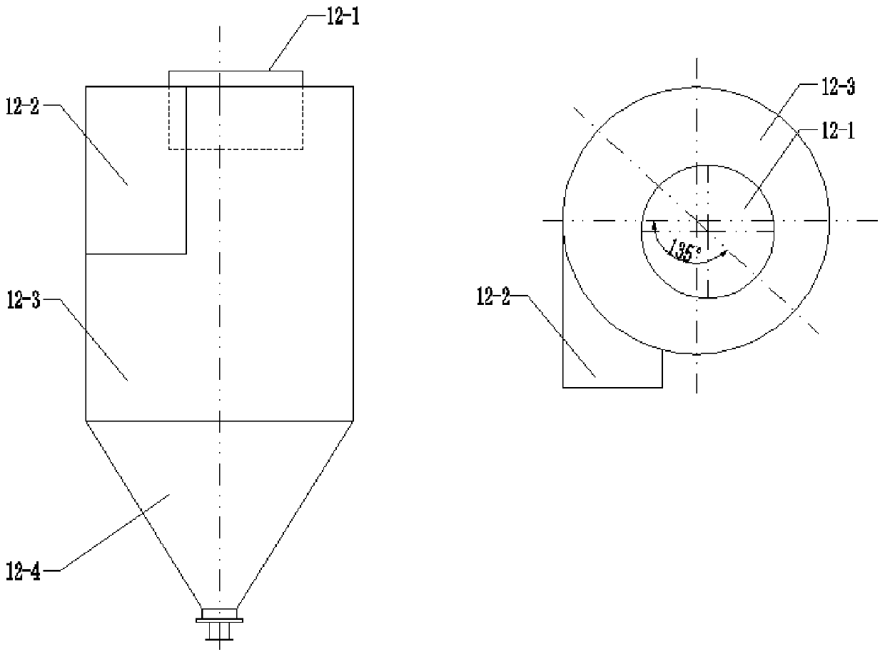
[0052] Specific implementation mode one: as figure 1 and 2 As shown, the SCR inlet flue gas pretreatment system and method of direct pyrolysis in a urea flue described in this embodiment:

[0053] The bed-fired coal-fired boiler equipped with the SCR flue gas denitrification system includes the bed-fired coal-fired boiler furnace 4, the burnout chamber 21, the convection tube bundle 5, the flue, the SCR inlet flue gas pretreatment system, the SCR device 17, and the economizer 18 , air preheater 19, etc.; the flue gas produced at the grate 2 of the layer-fired coal-fired boiler passes through the hearth 4 of the layer-fired coal-fired boiler, the burnout chamber 21, and sprays urea solution into the burnout chamber, and the high-temperature flue gas Under the action, pyrolysis forms NH3 mixed into the flue gas, and then the flue gas flows through the convection tube bundle 5, enters the flue gas pretreatment system at the SCR inlet, performs uniform temperature adjustment and...

specific Embodiment approach 2

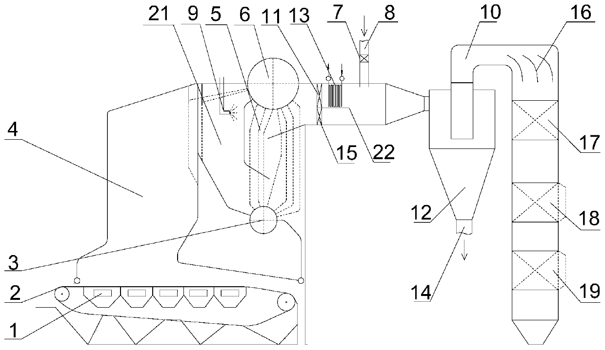
[0061] Specific implementation mode two: it differs from specific implementation scheme one in that: if image 3 , the cooling method of the temperature adjustment system of the flue gas pretreatment system at the SCR inlet, the cooling method is canceled by drawing low-temperature flue gas from the flue gas at the outlet of the boiler dust collector or the flue gas at the outlet of the air preheater to cool down; by adding a thermostat economizer Cool down.

[0062] The temperature regulation system of the flue gas pretreatment system at the SCR inlet, the cooling method is that the flue gas flowing out from the convection tube bundle 5 of the boiler is cooled by the temperature regulation economizer 13 . The cooling water on the working medium side of the temperature-adjusting economizer comes from the boiler feed water at the inlet of the boiler economizer 18, and the water heated up by the temperature-adjusting economizer 13 returns to the inlet of the boiler economizer 18...

specific Embodiment approach 3

[0063] Specific implementation mode three: the difference with specific implementation mode two is: if Figure 4 , in the transformation of old boilers, a smoke barrier 20 can be installed at the outlet of the boiler tube bundle 5, and the flue gas passes through the temperature adjustment system, the cyclone separator 12, the equalizer plate 16 and the SCR reaction device 17 from above the smoke barrier, Return to the bottom of the smoke baffle 20, and enter the original economizer 18 and air preheater 19 of the boiler, and then exit the boiler.

[0064] Other components and connections are the same as those in the second embodiment.


PUM


Abstract

The invention relates to an SCR inlet flue gas pre-treatment system and method, relates to boiler pollutant control technology, and are used for new construction or renovation projects of ultra-cleanNOx emission of grate-firing coal-fired boilers. The SCR inlet flue gas pre-treatment system comprises a temperature regulating system, a urea solution or ammonia water solution ejector, and a cycloneequalization system. The system adopts a heating way of extracting high-temperature flue gas from a hearth outlet and then introducing the high-temperature flue gas into a cyclone tube, and a coolingway of adding a temperature-regulating economizer or extracting low-temperature flue gas from flue gas at a boiler dust collector outlet or an air preheater outlet and then introducing the low-temperature flue gas into the cyclone tube through a cold flue, and the average temperature of SCR inlet flue gas is controlled within the working range of catalysts. A urea solution is ejected in a burnoutchamber through the urea solution ejector; an ammonia water solution is ejected at an inlet pipe of a cyclone separator through the ammonia water solution ejector; NH3 is produced under the action ofthe high-temperature flue gas and mixed into the flue gas. Under the combined action of a flow equalization board and the cyclone tube, the flue gas and NH3 are mixed uniformly to achieve the effectsof equal temperature, equal concentration field and equal velocity, thereby meeting the requirements on the temperature, concentration field and velocity field at an SCR inlet.

Description

technical field [0001] The invention relates to a method for pretreatment of flue gas at an SCR inlet by direct pyrolysis in a urea flue or direct decomposition in an ammonia flue, and relates to the technical field of pollutant control in bed-fired coal-fired boilers. Background technique [0002] In my country's energy structure, coal is the main fossil energy. Coal-fired industrial boilers are one of the major coal-consuming households. By the end of 2012, my country had 467,000 industrial boilers in use, with a total of 1.78 million steam tons. According to the data of the National Bureau of Statistics and the National Energy Administration, in 2012, the annual coal consumption of industrial boilers in the field of industrial heating was 650 million tons, accounting for about 20% of the national coal consumption. The flue gas emitted by coal-fired boilers is the main source of air pollutants NOx, and the NOx emitted by industrial boilers accounts for 15% to 20% of my c...

Claims


Application Information

Patent Timeline
IPC IPC(8): B01D53/90B01D53/56F23B70/00
CPCB01D53/8631B01D53/90B01D2251/2062B01D2251/2067F23B70/00
Inventor 杜谦高建民栾积毅赵义军冷浩崔朝阳赵广播吴少华秦裕琨
Owner HARBIN INST OF TECH
Why Eureka
Try Eureka