Composite electrolyte membrane, preparation method and application thereof, and solid-state lithium battery

A composite electrolyte membrane, solid electrolyte technology, applied in solid electrolytes, non-aqueous electrolytes, secondary batteries, etc., can solve the problems of lithium deposition to form lithium dendrites, continuous occurrence of interface side reactions, and high interface resistance, and achieve uniform concentration distribution. , The effect of reducing interface resistance and high safety

Active Publication Date: 2021-05-25
SHANGHAI ELECTRICGROUP CORP
View PDF13 Cites 6 Cited by
  • Summary
  • Abstract
  • Description
  • Claims
  • Application Information

AI Technical Summary

Problems solved by technology

[0006] In order to solve the problems of high interface resistance, continuous occurrence of interface side reactions, and formation of lithium dendrites by lithium deposition in the prior art of inorganic solid electrolytes, the present invention provides a composite electrolyte membrane, its preparation method and application, and a solid-state lithium battery.

Method used


Image

  • Composite electrolyte membrane, preparation method and application thereof, and solid-state lithium battery
  • Composite electrolyte membrane, preparation method and application thereof, and solid-state lithium battery
  • Composite electrolyte membrane, preparation method and application thereof, and solid-state lithium battery

Examples


Embodiment 1

[0050] (1) Preparation of solid electrolyte layer

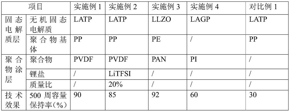
[0051] Mix LATP nanomaterials and NMP to obtain slurry B; apply slurry B to both sides of PP substrate (thickness 12 μm), dry, and form LATP layer with thickness 1 μm on both sides of PP substrate; obtain solid An electrolyte layer (thickness is 14 μm); wherein, the particle size of the LATP nanomaterial is 70 nm.

[0052] (2) Preparation of composite electrolyte membrane

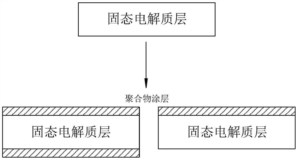
[0053] PVDF and NMP are mixed to obtain slurry A; slurry A is sprayed on both sides of the solid electrolyte layer obtained in step (1) (that is, sprayed on the LATP layer), dried, and formed on both sides of the solid electrolyte layer with a thickness of PVDF layer of 1 μm; the composite electrolyte membrane (thickness is 16 μm) is obtained, and the structure is as follows figure 1 shown.

Embodiment 2

[0055] (1) Preparation of solid electrolyte layer: same as step (1) in Example 1.

[0056] (2) Preparation of composite electrolyte membrane

[0057] Mix PVDF, LiTFSI and NMP to obtain slurry A, wherein the mass ratio of PVDF and LiTFSI is 5:1; slurry A is sprayed on both sides of the solid electrolyte layer obtained in step (1) (that is, sprayed on the LATP layer above), dry, and form a PVDF layer with a thickness of 1 μm on both sides of the solid electrolyte layer; that is, a composite electrolyte membrane (16 μm in thickness) with a structure such as figure 1 shown.

Embodiment 3

[0059] (1) Preparation of solid electrolyte layer

[0060] Mix LLZO nanomaterials and NMP to obtain slurry B; apply slurry B to both sides of a PE substrate (thickness 12 μm), dry, and form LLZO layers with a thickness of 1 μm on both sides of the PE substrate; that is, a solid Electrolyte layer (14 μm in thickness); wherein, the particle size of the LLZO nanomaterial is 70 nm.

[0061] (2) Preparation of composite electrolyte membrane

[0062] PAN and NMP are mixed to obtain slurry A; slurry A is sprayed on both sides of the solid electrolyte layer obtained in step (1) (that is, sprayed on the LLZO layer), dried, and formed on both sides of the solid electrolyte layer with a thickness of A PAN layer of 1 μm; the composite electrolyte membrane (16 μm in thickness) is obtained, and the structure is as follows figure 1 shown.


PUM

PropertyMeasurementUnit
thicknessaaaaaaaaaa
thicknessaaaaaaaaaa
particle sizeaaaaaaaaaa

Abstract

The invention discloses a composite electrolyte membrane, a preparation method and application thereof, and a solid-state lithium battery. The composite electrolyte membrane comprises a solid electrolyte layer, wherein one side or two sides of the solid electrolyte layer are coated with a polymer coating; the solid electrolyte layer includes an inorganic solid electrolyte. The composite electrolyte membrane can reduce interface resistance, inhibit interface side reaction and relieve lithium deposition; the solid-state lithium battery based on the composite electrolyte membrane is good in cycle performance and good in safety.

Description

technical field [0001] The invention relates to a composite electrolyte membrane, its preparation method and application, and a solid-state lithium battery. Background technique [0002] As an important electrochemical energy storage device, lithium-ion batteries have been widely used in consumer electronics, power batteries, energy storage and other fields, and the market demand is increasing year by year. With the increasing demand for lithium-ion batteries, consumers have put forward higher and higher requirements for the performance of lithium-ion batteries, and the pain points of lithium-ion batteries have become more and more prominent. The core problem is the incompatibility between energy density and safety. The improvement of the energy density of lithium-ion batteries has been limited, and it is generally believed that the upper limit of energy density is around 300Wh / kg. And in the process of increasing the energy density, it shows a trend that the higher the ene...

Claims


Application Information

Patent Timeline
Patent Type & Authority Applications(China)
IPC IPC(8): H01M10/0562H01M10/0525H01M10/42
CPCH01M10/0562H01M10/0525H01M10/4235H01M2300/0068Y02E60/10
Inventor 耿振廖文俊王中驰
Owner SHANGHAI ELECTRICGROUP CORP
Why Eureka
Try Eureka