Solid electrolytic capacitor

a solid electrolytic capacitor and capacitor element technology, applied in the direction of electrolytic capacitors, hybrid capacitor terminals, hybrid cases/housings/encapsulations, etc., can solve the problems of capacitor elements, poor adhesion of external electrodes, and tendency to peel off, so as to reduce the peeling of capacitor elements and enhance reliability

Active Publication Date: 2017-12-21
MURATA MFG CO LTD
View PDF7 Cites 20 Cited by
  • Summary
  • Abstract
  • Description
  • Claims
  • Application Information

AI Technical Summary

Benefits of technology

[0009]Another object of the present invention is to provide a solid electrolytic capacitor which can suppress peeling of a capacitor element stacked on a leading conductor layer off the leading conductor layer and enhance reliability.

Problems solved by technology

If an external electrode is formed to extend from an end surface to a main surface without processing of an end surface (or cut surface) of the cut resin mold, the external electrode poorly adheres and tends to peel off at a boundary between the end surface of the resin and the main surface of the resin.
In such a configuration, however, in an environment of high temperature and high humidity and when mounting on a mounting substrate, the capacitor element expands due to heat or the like and the leading conductor layer may peel off the capacitor element.

Method used


Image

  • Solid electrolytic capacitor
  • Solid electrolytic capacitor
  • Solid electrolytic capacitor

Examples


first embodiment

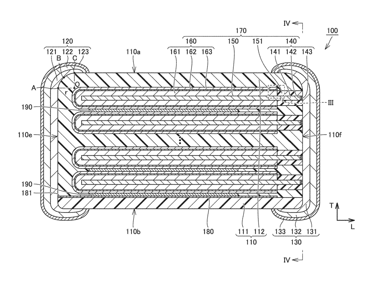
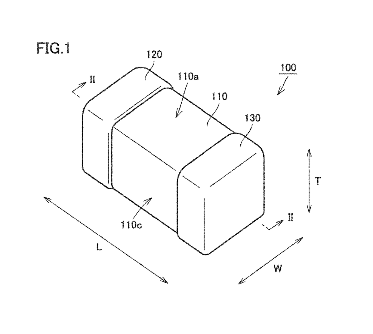
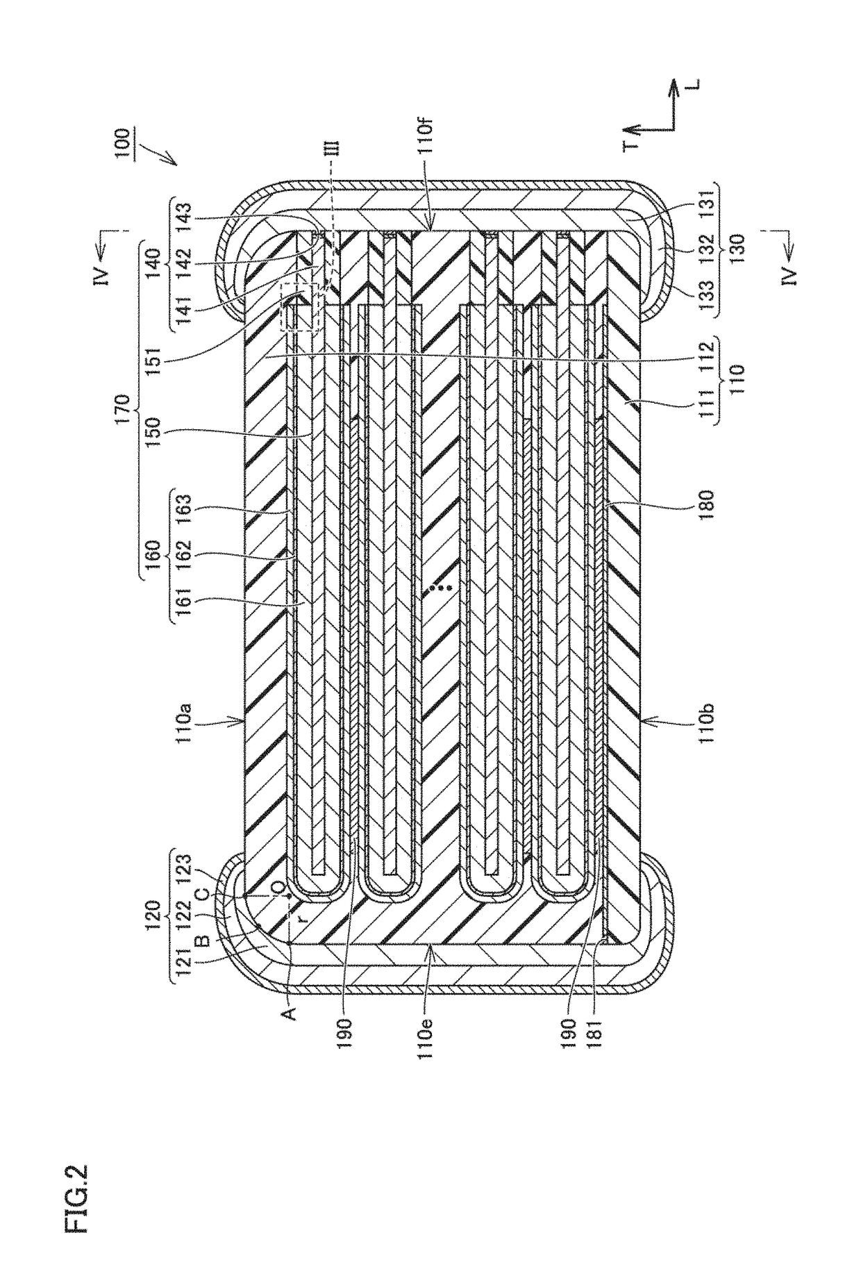
[0054]FIG. 1 is a perspective view of a solid electrolytic capacitor according to a first embodiment. FIG. 2 is a cross-sectional view of the solid electrolytic capacitor taken along a line II-II shown in FIG. 1. FIG. 3 is an enlarged cross-sectional view of a portion III shown in FIG. 2. FIG. 4 is a cross-sectional view of the solid electrolytic capacitor taken along a line IV-IV shown in FIG. 2. With reference to FIG. 1 to FIG. 4, a solid electrolytic capacitor 100 according to the first embodiment will be described.

[0055]As shown in FIG. 1 to FIG. 4, solid electrolytic capacitor 100 according to the embodiment has a generally rectangular parallelepiped external shape. Solid electrolytic capacitor 100 has external dimensions for example of 3.5 mm in lengthwise direction L, 2.8 mm in widthwise direction W, and 1.9 mm in heightwise direction T.

[0056]Solid electrolytic capacitor 100 includes a plurality of capacitor elements 170, a leading conductor layer 180, an insulating resin bod...

exemplary experiment 1

[0153]Hereinafter, exemplary experiment 1 will be described which investigated a relationship between a surface roughness of an end surface of the insulating resin body and a rate of occurrence of peeling of an external electrode.

[0154]The insulating resin body had an end surface with surface roughnesses (Ra) of 8.3 μm in Example 1, 5.1 μm in Example 2, 2.2 μm in Example 3, 9.2 μm in Comparative Example 1, 0.4 μm in Comparative Example 2 and 0.1 μm in Comparative Example 3. Whether an external electrode formed by barrel plating peeled or not was investigated. 100 samples were prepared for each of Example 1, Example 2, Comparative Example 1 and Comparative Example 2. The surface roughness (Ra) of the end surface of the insulating resin body is determined by removing an external electrode with a stripping agent such as an en strip or a mel strip to expose an end surface of the insulating resin body, and measuring the surface roughness (Ra) using a laser microscope at a position of a c...

exemplary experiment 2

[0160]Exemplary experiment 2 will be described which was conducted to investigate how the length of the insulating resin layer influences the solid electrolytic capacitor's electrostatic capacity, ESR and reliability.

[0161]A ratio of the length of the insulating resin layer in lengthwise direction L to the length of the insulating resin body in lengthwise direction L was 0.025 in Example 4, 0.05 in Example 5, 0.1 in Example 6, 0.15 in Example 7, 0.2 in Example 8, 0.25 in Example 9, 0.3 in Example 10, 0.35 in Example 11, 0.4 in Example 12, 0.45 in Example 13, 0.5 in Example 14, 0.01 in Comparative Example 4, 0.7 in Comparative Example 5, and 0.9 in Comparative Example 6. Each solid electrolytic capacitor's electrostatic capacity (μF), ESR (me) and leakage current (μA) were measured.

TABLE 2ratio of lengthof insulatingresin layer tolength ofinsulatingelectrostaticleakageresin bodycapacity (μF)ESR (mΩ)current (μA)example 40.02533.925.80.08example 50.0533.225.30.1example 60.133.525.60.05...


PUM


Abstract

A solid electrolytic capacitor that includes a plurality of capacitor elements each including an anode portion, a dielectric layer, and a cathode portion having a solid electrolyte layer and a current collector layer; a leading conductor layer; an insulating resin body; a first external electrode; and a second external electrode. The plurality of capacitor elements are stacked in layers, with mutually adjacent capacitor elements having their respective current collector layers connected to each other. The current collector layer of only the capacitor element adjacent to the leading conductor layer is connected to the leading conductor layer. The first external electrode is connected to the leading conductor layer at the first end surface.

Description

CROSS REFERENCE TO RELATED APPLICATIONS[0001]The present application claims priority to Japanese Patent Application No. 2016-118971, filed Jun. 15, 2016, Japanese Patent Application No. 2016-118973, filed Jun. 15, 2016, Japanese Patent Application No. 2016-118974, filed Jun. 15, 2016, Japanese Patent Application No. 2016-118975, filed Jun. 15, 2016, Japanese Patent Application No. 2017-112108, filed Jun. 6, 2017, and Japanese Patent Application No. 2017-115326, Jun. 12, 2017, the entire contents of each of which are incorporated herein by reference.BACKGROUND OF THE INVENTIONField of the Invention[0002]The present invention relates to a solid electrolytic capacitor.Description of the Background Art[0003]A solid electrolytic capacitor described in International Publication No. 2013 / 088954 includes a stack of a plurality of capacitor elements, an anode terminal bonded to a side surface of the stack, and a cathode terminal bonded to a portion of a main surface of the stack and a side s...

Claims


Application Information

Patent Timeline
Patent Type & Authority Applications(United States)
IPC IPC(8): H01G11/28H01G11/70H01G11/46H01G11/56H01G11/78H01G11/74
CPCH01G11/28H01G11/56H01G11/46H01G11/78H01G11/74H01G11/70H01G9/004H01G9/012H01G9/15H01G9/08H01G9/26H01G9/008
Inventor DEMIZU, HIROYUKIOSHIUMI, KENICHISUZUKI, TOMOHIROYOSHIDA, SHINYASANO, TADAHISAFUJIMOTO, KOJIYAMAMOTO, TSUYOSHIUEDA, YOSHINORIOTANI, SHINJI
Owner MURATA MFG CO LTD
Why Eureka
Try Eureka