Method for operating an electrically operated or also electrically operable motor vehicle and motor vehicle

Active Publication Date: 2018-01-04
AUDI AG
View PDF3 Cites 16 Cited by
  • Summary
  • Abstract
  • Description
  • Claims
  • Application Information

AI Technical Summary

Benefits of technology

[0022]c2) the braking component of the trailer is decreased in favor of an increased level of e

Problems solved by technology

However, if with an electrically operated or also electrically operable motor vehicle, for example the entire mass will deviate based on the load attached to the roof, and/or on the load of a trailer optionally attached to the motor vehicle, so that it deviates significantly from an assumed “normal value” and the operating strategy that is calculated according to prior art is then no longer optimal and the energy that can be possible obtained free of charge with recuperation is “destroyed”.
Another disadvantage in such a case is that since sustained deceleration is not available when traveling on a downhill slope with a trailer due to the increased deceleration requirement, namely because the en

Method used


Image

  • Method for operating an electrically operated or also electrically operable motor vehicle and motor vehicle
  • Method for operating an electrically operated or also electrically operable motor vehicle and motor vehicle
  • Method for operating an electrically operated or also electrically operable motor vehicle and motor vehicle

Examples


example 1

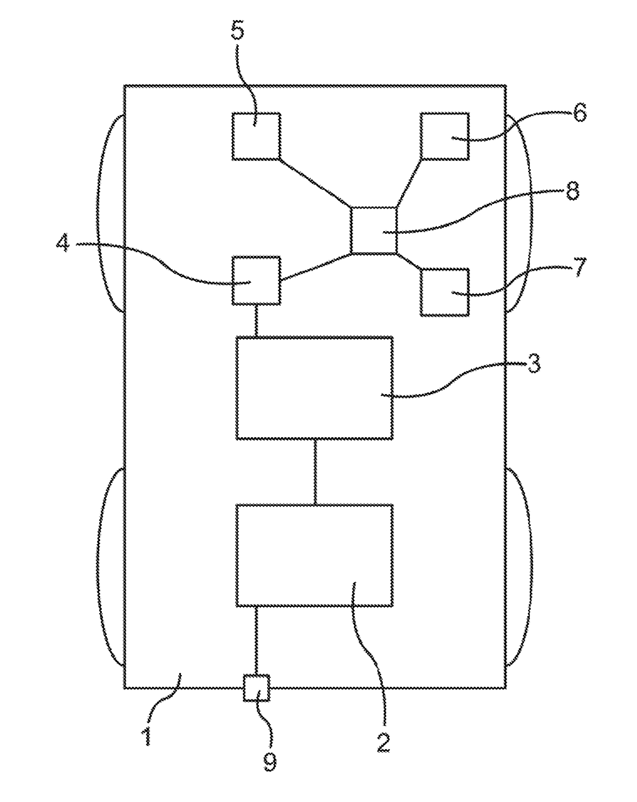
[0142]The trailer is attached to the electrified motor vehicle 1 and detected by a sensor system 5 on the vehicle-side; as an alternative, the driver can “notify” the electrified motor vehicle 1 (for example via the input device 6) that the electrified motor vehicle 1 is connected to a trailer, or will be connected to a trailer before the next upcoming trip. At the same time, the course to be traveled by the electrified motor vehicle 1 during the next trip is known (for example based on the input of the driver with a navigation device 7).

[0143]The electrified motor vehicle 1 is connected to a charging station, a power supply network, or a storage device for electric current supply and the rechargeable electric energy storage device 3 is recharged while taking into account the additional mass of the trailer to such an extent or discharged so far (until a calculated or estimated target state is reached) that the electric energy that can be obtained from each deceleration processing wi...

example 2

[0147]In this example, the trailer is not attached before the stationary charging and the driver also does not notify the electrified motor vehicle 1 that it is attached after the charging. In such a case, the rechargeable energy storage device 3 of the electrified vehicle 1 can be charged by simply using only a “normal value” for the total mass of the motor vehicle and / or a “normal value” for the air resistance until an assumed charging state is reached, in particular while taking into account the “normal” energy recuperative recovery conduct of the electrified vehicle 1.

[0148]This “assumed charging state” is in this case selected so that in each case, a minimum amount could be obtained by means of recuperation during all of the downhill travel with the deceleration processes required for this purpose.

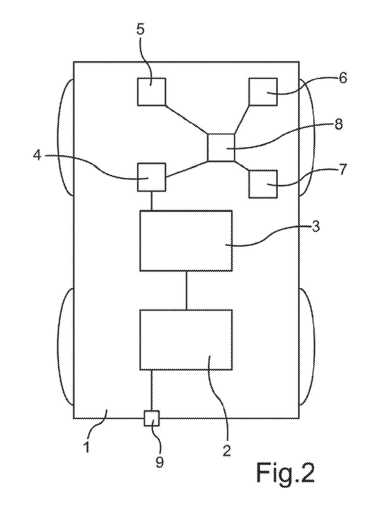
[0149]At the beginning of the trip, the trailer is connected to the electrified motor vehicle 1, which is detected by a sensor system 5. Alternatively or in addition to this, the pres...


PUM


Abstract

A method for operating an electrically operated or also electrically operable motor vehicle provided with a rechargeable electric energy storage device associated with the drive motor of the motor vehicle. A target charging state is determined for the energy storage device and an operating strategy is determined for a route that is calculated, entered or predicted for the next trip, by which recuperative deceleration is enabled with a specifiable minimum amount for deceleration processes occurring along the route. A total mass of the motor vehicle, including optionally a trailer connected to the motor vehicle, deviating from an input normal value and an air resistance of the motor vehicle deviating from a predetermined normal value are taken into account.

Description

FIELD[0001]The present invention relates to a method for operating an electrically operated or also electrically operable motor vehicle.BACKGROUND[0002]Various methods and systems are known from prior that can be used in order to plan at the start of the trip a time-optimized or an energy-optimized operating strategy for operating an electrically operated or also electrically operable motor vehicle, such for example a purely electrically operated motor vehicle (Battery Operated Vehicle, or BOV), or a hybrid electric motor vehicle (HEV), or a plug-in hybrid electric vehicle (PHEV).[0003]Furthermore, various methods and systems are also known for planning the optimum operating strategy of an electrical operated or also electrically operable motor vehicle before starting a trip.[0004]For example DE 10 2009 052 531 A describes a method for estimating the range of a motor vehicle based on the amount of energy that is available and detectable in a motor vehicle, wherein the driver determi...

Claims


Application Information

Patent Timeline
IPC IPC(8): B60L15/20B60L7/18B60L11/18
CPCB60L15/2045B60L11/1862B60L7/18B60L11/1809B60L15/2009B60L2250/18B60L2260/54B60L2240/645B60L2240/68B60L2240/16B60L2240/26B60L2240/54B60L2240/42B60L2240/66B60L7/10B60L2200/28B60L2240/662B60L2250/12B60L2260/52B60W10/08B60W10/184B60W10/26B60W10/30B60W30/18127B60W50/0097B60W2530/10B60W2530/16B60W2540/30B60W2710/244B60W20/12B60W20/14B60L53/00B60L53/50B60L58/13B60W2552/05B60W2555/20B60W2556/50G01C21/3469Y02T10/62Y02T10/64Y02T10/70Y02T10/7072Y02T10/72Y02T90/12Y02T90/14Y02T90/16
Inventor GEUMATTHIASVOLKMAR, KAI
Owner AUDI AG
Why Eureka
Try Eureka