Rock anchor foundation structure suitable for mountain photovoltaic module and construction method of rock anchor foundation structure

a technology of photovoltaic modules and rock anchors, which is applied in the direction of machine supports, heat collector mountings/supports, light and heating equipment, etc., can solve the problems of increasing construction costs and corresponding construction difficulties in mountain area construction, and achieve the effect of lowering construction costs

Active Publication Date: 2018-01-04
POWERCHINA HUADONG ENG COPORATION LTD
View PDF4 Cites 15 Cited by
  • Summary
  • Abstract
  • Description
  • Claims
  • Application Information

AI Technical Summary

Benefits of technology

[0016]The present invention has the beneficial effects that: the hollow anchor rod and a grouting technology which, are suitable for various terrains are adopted, and the concrete protective bearing platform is utilized to protect a rock anchor system, so that the construction efficiency of the mountain photovoltaic power station foundation is improved, the construction cost is lowered, and the capability of the foundation of bearing the loads (loads of the photovoltaic panel and the bracket) is improved at the same time.

Problems solved by technology

However, most of construction regions of the mountain photovoltaic power stations are three-no-environments without roads, power and water; and with adoption of ordinary threaded steel and manganese silicon steel as anchor bar materials of the anchor rod foundations, a great deal of electric welding cutting work needs to be carried out necessarily, large-power diesel generators certainly will be equipped in the site construction, and corresponding construction difficulty and the building cost are increased in mountain area construction.

Method used


Image

  • Rock anchor foundation structure suitable for mountain photovoltaic module and construction method of rock anchor foundation structure
  • Rock anchor foundation structure suitable for mountain photovoltaic module and construction method of rock anchor foundation structure
  • Rock anchor foundation structure suitable for mountain photovoltaic module and construction method of rock anchor foundation structure

Examples


Embodiment Construction

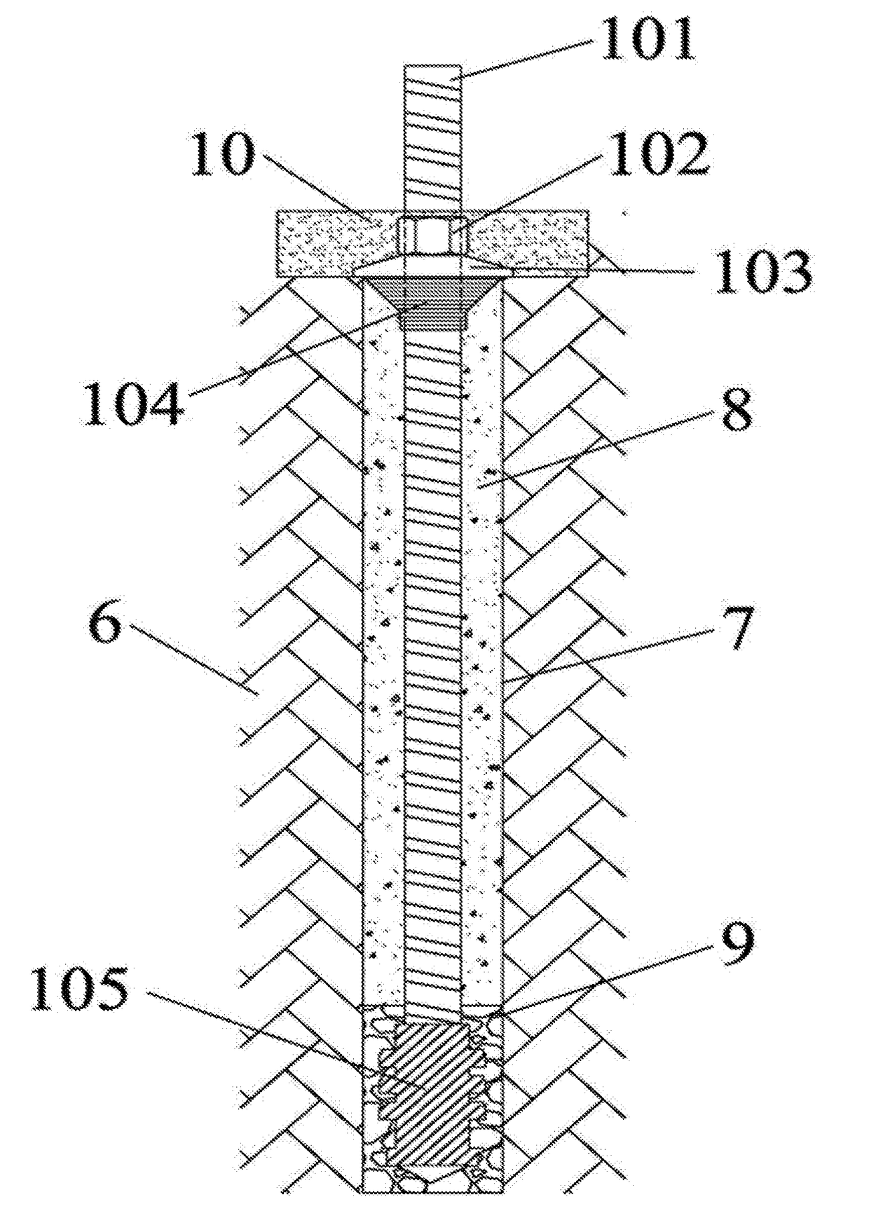
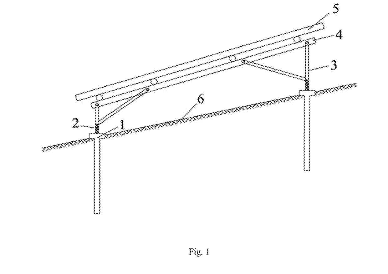
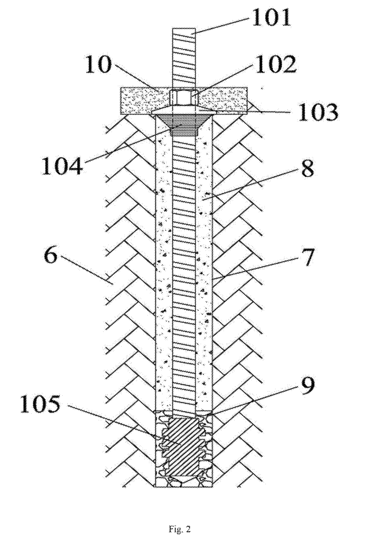
[0019]As shown in FIG. 1 and FIG. 2, the present embodiment is a rock anchor foundation structure suitable for a mountain photovoltaic module. The rock anchor foundation structure comprises a drill hole 7 drilled in a rock slope 6, an anchor rod module 1 arranged in the drill hole, a photovoltaic power station module and a hollow connecting steel pipe 2 used for connecting the photovoltaic power station module with the anchor rod module 1.

[0020]The photovoltaic power station module comprises a beam 4, a bracket 3 hinged to the lower side of the beam 4 and a photovoltaic cell panel 5 arranged at the upper pan of the beam, and the bottom of the bracket 3 is welded with the hollow connecting steel pipe 2.

[0021]The anchor rod module 1 comprises a hollow anchor rod 101 inserted into the drill hole 7 and provided with continuous waveform threads on the surface, a plastic anchor head module 105, a stop-grouting plug 104, a steel cushion plate 103 and a fastening nut 102, and the plastic an...


PUM

PropertyMeasurementUnit
thicknessaaaaaaaaaa
solar energyaaaaaaaaaa
electric energyaaaaaaaaaa

Abstract

The present invention relates to a rock anchor foundation structure suitable for a mountain photovoltaic module and a construction method of the rock anchor foundation structure. A technical solution of the present invention is as follows: the rock anchor foundation structure comprises a drill hole drilled in a rock slope, an anchor rod module arranged in the drill hole and a photovoltaic power station module. The photovoltaic power station module is connected with the anchor rod module through a hollow connecting steel pipe; the photovoltaic power station module comprises a bracket welded on the top of the hollow connecting steel pipe, a beam mutually hinged with the top of the bracket and a photovoltaic cell panel arranged at the upper part of the beam. The rock anchor foundation structure of the present invention is suitable for the technical fields of around treatment and foundation engineering design.

Description

FIELD OF THE INVENTION[0001]The present invention belongs, to the technical fields of ground treatment and foundation engineering design and particularly relates to a rock anchor foundation structure suitable for a mountain photovoltaic module and a construction method of the rock anchor foundation structure.BACKGROUND OF THE INVENTION[0002]A photovoltaic cell panel is a device for converting solar energy into electric energy and is a core member of a photovoltaic power station. Photovoltaic power station foundation engineering is to transfer loads of the photovoltaic cell panel and a bracket thereof into a structure in a stratum. A foundation form of current ground photovoltaic power stations may be mainly categorized into a screw pile foundation, an independent: foundation, a strip foundation and an anchor rod foundation, and photovoltaic brackets adopt rock anchor (rod) foundations mostly in mountainous and hilly lands due to the characteristics of burying depth of rock formation...

Claims


Application Information

Patent Timeline
Patent Type & Authority Applications(United States)
IPC IPC(8): E02D5/80F16M11/22H02S20/10E02D27/50
CPCE02D5/80E02D27/50F16M11/22E02D2300/002E02D2250/0023E02D2300/0006E02D2300/0029H02S20/10E02D5/76F24S25/12F24S25/617Y02E10/47Y02E10/50E21D21/0026E21D21/008F16B13/141
Inventor SUN, MIAOJUNWANG, MINGYUANDU, WENBONI, WEIDAXIONG, XIAO
Owner POWERCHINA HUADONG ENG COPORATION LTD
Why Eureka
Try Eureka