Scanning electron microscope

a scanning electron microscope and electron microscope technology, applied in the field of scanning electron microscope, can solve the problems of high energy resolution of analyzer, limited range of energies, long measuring time, etc., and achieve the effect of the same energy resolution

Inactive Publication Date: 2018-01-04
NGR
View PDF0 Cites 12 Cited by
  • Summary
  • Abstract
  • Description
  • Claims
  • Application Information

AI Technical Summary

Benefits of technology

[0009]According to the above-described embodiments, a parallel detection in a wide energy range can be achieved. In addition, the same energy resolution as that of a conventional energy analyzing system can be obtained.

Problems solved by technology

This type of analyzer has a high energy resolution, but has a strictly limited range of energies that can be detected at a time, because this type of analyzer is configured to detect, at its outlet side, only electrons which have passed through a narrow space between electrodes.
Performing the serial detection entails a complicated control for obtaining a spectral distribution over an entire energy range.
Moreover, it takes a long measuring time.

Method used


Image

  • Scanning electron microscope
  • Scanning electron microscope
  • Scanning electron microscope

Examples


Embodiment Construction

[0015]Embodiments of the present invention will be described below with reference to the drawings.

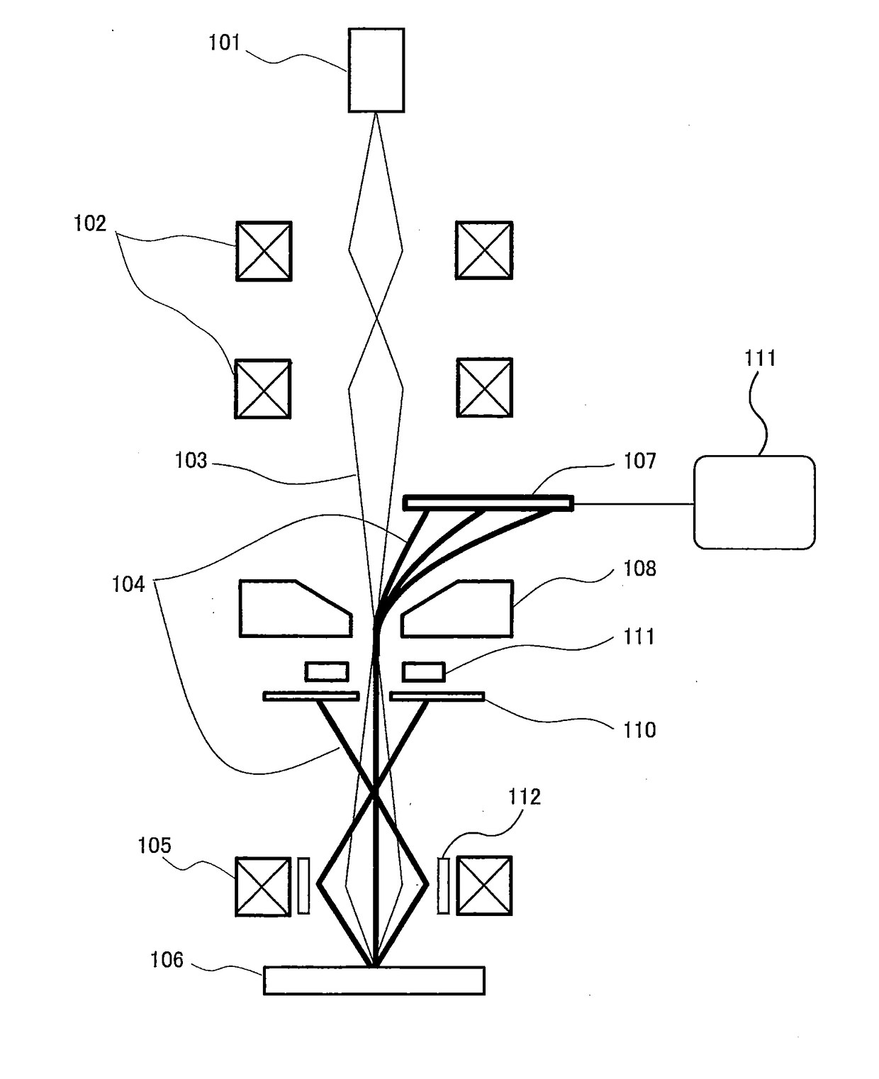
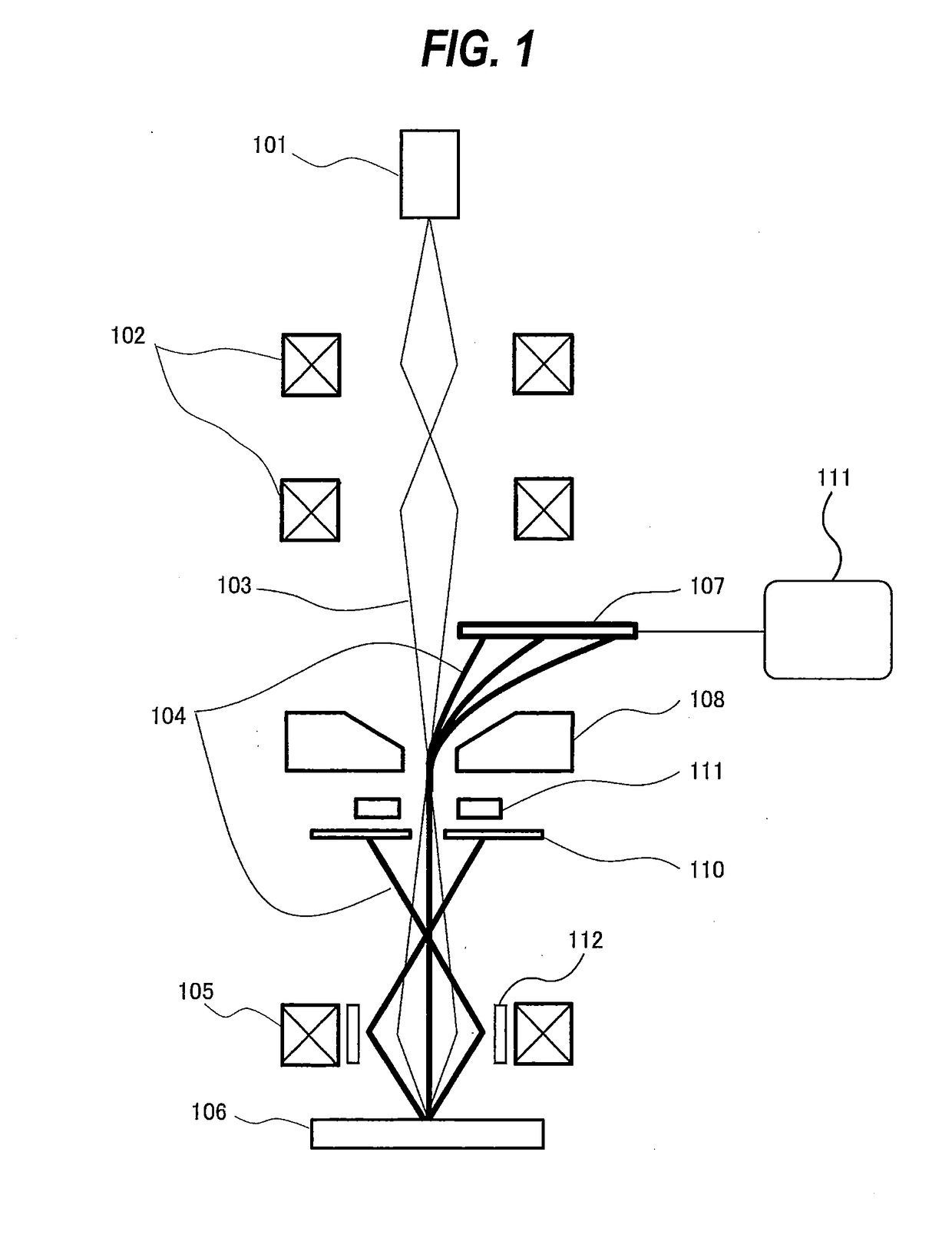
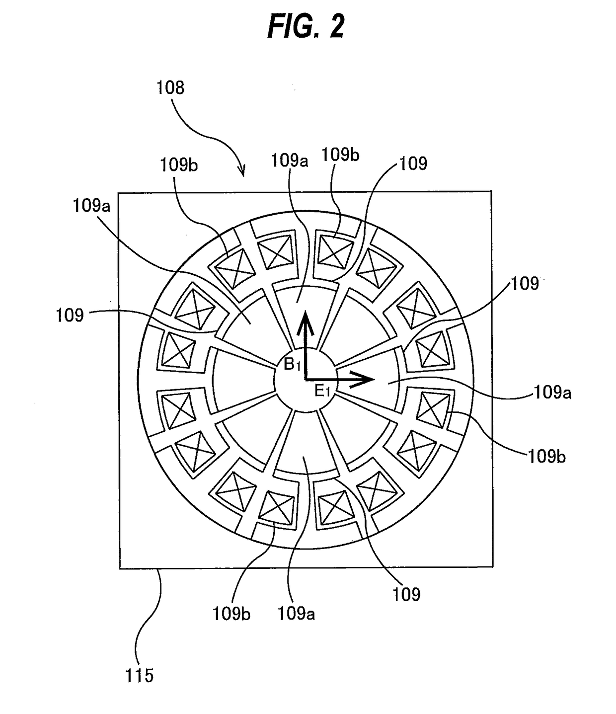
[0016]FIG. 1 is a schematic view showing a basic structure of a scanning electron microscope according to an embodiment of the present invention. In FIG. 1, an electron gun 101, serving as an electron beam source, generates a primary electron beam 103, which is firstly converged by a condenser lens system 102 composed of multiple lenses. The primary electron beam 103 passes through a Wien filter 108 and is focused by an objective lens 105 onto a specimen 106. The primary electron beam 103 is deflected by a deflector 112 so as to scan a surface of the specimen 106.

[0017]A diameter of a back-scattered electron beam 104, emitted from the specimen 106, is restricted appropriately by a back-scattered electron diaphragm 110. This back-scattered electron diaphragm 110 has an aperture which provides a light source as viewed from an energy analyzing system. The back-scattered electron beam 104 t...


PUM


Abstract

A scanning electron microscope including: an electron beam source for generating a primary electron beam; an electron optical system configured to direct the primary electron beam to a specimen while focusing and deflecting the primary electron beam; and an energy analyzing system capable of performing parallel detection of an energy spectrum of back-scattered electrons emitted from the specimen is disclosed. The energy analyzing system includes: a Wien filter configured to separate the back-scattered electrons from a beam axis and analyze energies of the back-scattered electrons; and an array detector configured to detect the back-scattered electrons that have passed through the Wien filter. The Wien filter includes a plurality of electromagnetic poles, center-side ends of the plurality of electromagnetic poles have tapered surfaces, respectively, and the tapered surfaces form an exit of the Wien filter through which the back-scattered electrons pass out.

Description

BACKGROUND[0001]The present invention relates to a scanning electron microscope, and more particularly to a Wien filter which can analyze energies of back-scattered electrons emitted from a specimen.[0002]A scanning electron microscope for the purpose of observing semiconductor devices has been developed. With a trend toward finer and finer device patterns to be observed, multilayered structure of patterns is progressing. Under such circumstances, it is effective for the scanning electron microscope to use a high acceleration voltage capable of generating a high penetration force and to observe back-scattered electrons having appropriate energies determined depending on a depth from a surface of a specimen which is an object of the observation. For this purpose, it is necessary to freely select an energy range of the back-scattered electrons in accordance with the specimen to be observed, and to generate an image of the back-scattered electrons using only signals within such a range...

Claims


Application Information

Patent Timeline
Patent Type & Authority Applications(United States)
IPC IPC(8): H01J37/244H01J37/22H01J37/28
CPCH01J37/244H01J37/28H01J2237/24564H01J2237/24475H01J37/222H01J37/05H01J2237/2446H01J2237/24485
Inventor KATO, MAKOTOTAKASHIMA, SUSUMUKUBOTA, KAZUFUMIZENYOUJI, KAORUYAMAZAKI, YUICHIRO
Owner NGR
Why Eureka
Try Eureka