Adjustable magnetic buoyancy gravity compensator

a compensator and magnetic buoyancy technology, applied in the direction of magnetic circuit rotating parts, instruments, magnetic circuit shape/form/construction, etc., can solve the problems of high structural complexity, difficult to equalize the gravitational load among, and high stiffness requirements, and achieve the effect of widening the range of adjustmen

Active Publication Date: 2018-01-11
SHANGHAI MICRO ELECTRONICS EQUIP (GRP) CO LTD
View PDF1 Cites 2 Cited by
  • Summary
  • Abstract
  • Description
  • Claims
  • Application Information

AI Technical Summary

Benefits of technology

[0019]The adjustable magnetic gravity compensator according to the present invention incorporates the adjustment mechanism and the central cylindrical magnet consisting of a number of arc magnets which can move inward and outward concentrically under the driving effect of the adjustment mechanism. In this way, inner and outer radii of the central cylindrical magnet and hence magnetic circuit between the central cylindri

Problems solved by technology

However, as this solution requires three such magnetic gravity compensators to support the fine-motion stage 4′, it is difficult to equally divide the gravitational load among them.
The solution also suffers from high structural complexity, hig

Method used


Image

  • Adjustable magnetic buoyancy gravity compensator
  • Adjustable magnetic buoyancy gravity compensator
  • Adjustable magnetic buoyancy gravity compensator

Examples


embodiment 1

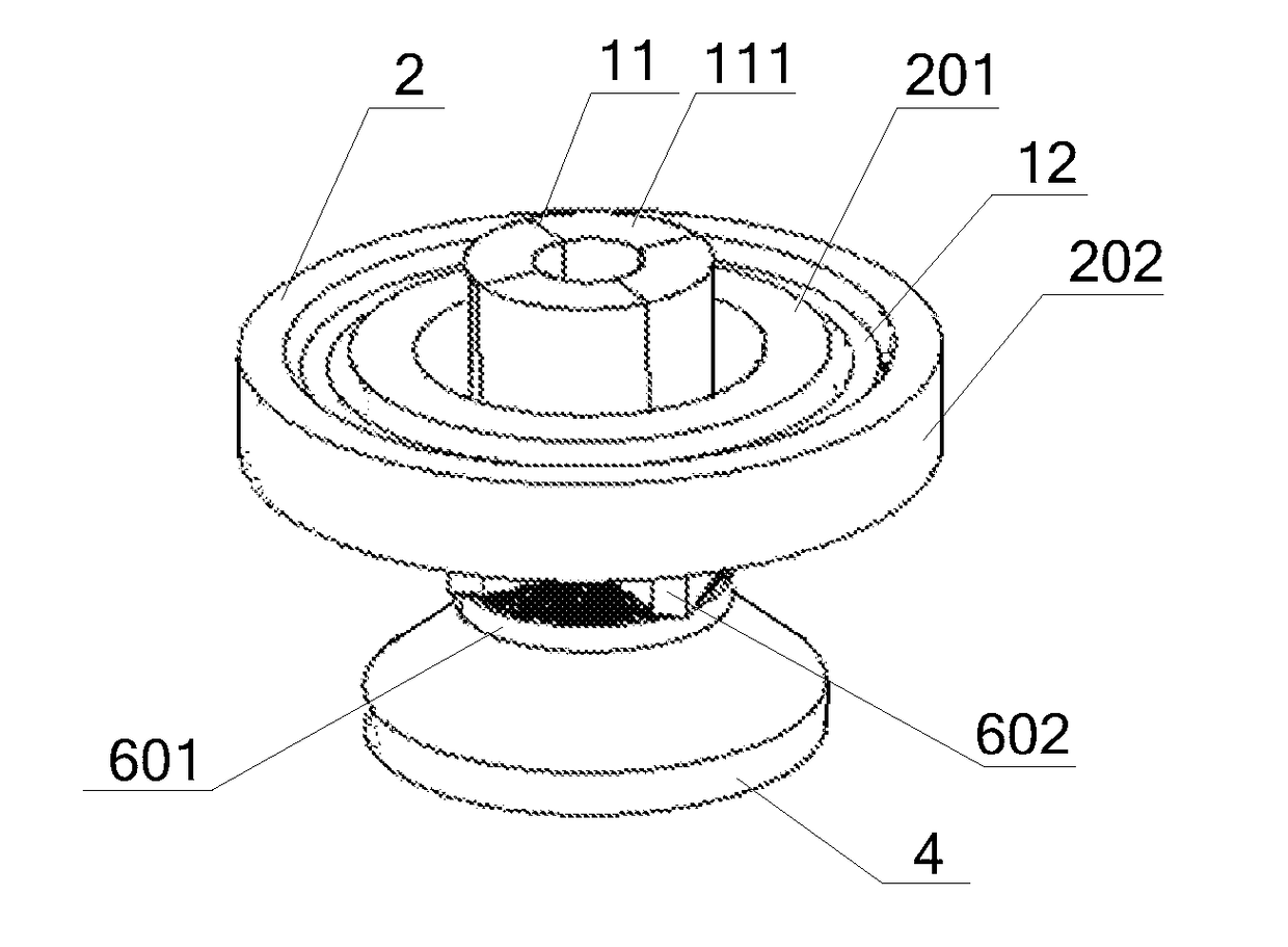
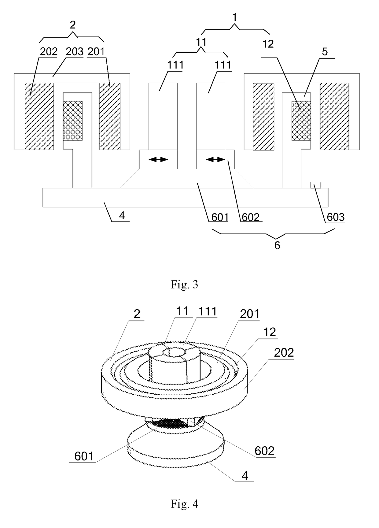
[0033]As shown in FIG. 3, an adjustable magnetic gravity compensator according to this embodiment includes a stator 1, a rotor 2, a base 4 and an adjustment mechanism 6. The stator is disposed on the base 4, and the rotor 2 is magnetically levitated with respect to the stator 1. The stator 1 includes a coil of a voice coil motor 12 and a central cylindrical magnet 11. The coil 12 is fixed to the base 4 by a coil frame 5, and the central cylindrical magnet 11 consists of at least two arc magnets 111 each magnetized along an axis of the central cylindrical magnet 11. The arc magnets cooperate with the rotor 2 to provide a stable and less stiff basic levitation force. The adjustment mechanism 6 is secured to the base 4 at the bottom and is fixedly connected to the arc magnets 111 at the top so that it can drive the arc magnets 111 to move inward and outward concentrically, i.e., radially with respect to a center of the central cylindrical magnet 11. The rotor 2 is magnetized radially. ...

embodiment 2

[0039]As shown in FIG. 9, this embodiment differs from Embodiment 1 in that, in the adjustment mechanism 6 according to this embodiment, the driver 601 is a frustum, with the followers 602 being wedge-shaped blocks corresponding to the frustum. The adjuster 603 is disposed on the base 4, and when it is rotated, the frustum is caused to move upward or downward, driving the followers 602 and the arc magnets 111 to move inward and outward concentrically. The close fit between the frustum and the wedges allows a higher adjustment accuracy.

embodiment 3

[0040]As shown in FIG. 10, this embodiment differs from Embodiments 1 and 2 in that, in the adjustment mechanism 6 according to this embodiment, the driver 601 is a cylindrical base with a central protrusion while the followers 602 are slide blocks. They are articulated together with movable hinges 604. The adjuster 603 includes an adjusting nut 6031 and a screw rod 6032 engaged with the adjusting nut 6031. The screw rod 6032 is provided inside the cylindrical base and is connected to the movable hinges 604 and the base 4 at the top and bottom, respectively. The engagement between the adjusting nut 6031 and the screw rod 6032 allows a higher adjustment flexibility.


PUM


Abstract

A magnetic gravity compensator comprises a stator (1), a rotor (2), a base (4) and an adjustment mechanism (6). The stator (1) is disposed on the base (4), and the rotor (2) is levitated with respect to the stator (1). The stator (1) comprises a central cylindrical magnet (11) that is fixed to the base (4) by the adjustment mechanism (6) and consists of at least two arc magnets (111). The adjustment mechanism (6) has a first end fixed to the base (4) and a second end securely connected to the at least two arc magnets (111). The adjustment mechanism (6) is configured to drive the at least two arc magnets (111) to synchronously move radially with respect to a central axis of the central cylindrical magnet (11) so as to change a magnetic circuit between the central cylindrical magnet (11) and the rotor (2), and thereby adjust a magnetic levitation force between the stator (1) and the rotor (2).

Description

TECHNICAL FIELD[0001]The present invention relates to magnetic gravity compensators used in photolithography and, more particularly, to an adjustable magnetic buoyancy gravity compensator.BACKGROUND[0002]A photolithography tool is a device for exposing a mask pattern onto a wafer, primarily used in the fabrication of integrated circuits (ICs) and other micro-devices. During the exposure of the mask pattern, the mask and wafer are moved simultaneously relative to a projection system and a projection light beam.[0003]Increasing integration of large-scale IC devices leads to demand for photolithography tools with higher resolutions and smaller critical dimensions. At present, photolithography tools have evolved into combinations of internal and external worlds. In such a photolithography tool, a wafer stage, a mask stage and an illumination system for them are damped as three independent worlds. For a fine-motion module, effective damping of a wafer chuck or a mask chuck is necessary f...

Claims


Application Information

Patent Timeline
IPC IPC(8): F16C29/02H02K1/27G03F7/20H02K41/03F16C32/06
CPCF16C29/025F16C32/0603G03F7/70816H02K1/27H02K41/031G03F7/70758H02K33/18G03F7/20
Inventor JI, HANCHUANCHEN, QINGSHENG
Owner SHANGHAI MICRO ELECTRONICS EQUIP (GRP) CO LTD
Why Eureka
Try Eureka