
Printing agent, printed fabric, and method for producing printing agent

a printing agent and fabric technology, applied in dyeing process, inks, textiles and paper, etc., can solve the problems of coarse particles in ink, increased the likelihood of screen clogging, ink ejection failure, etc., to reduce the amount of coarse particles, excellent printing properties, and high fastness to rubbing

Active Publication Date: 2018-01-18
DAINIPPON INK & CHEM INC
View PDF0 Cites 3 Cited by
  • Summary
  • Abstract
  • Description
  • Claims
  • Application Information

AI Technical Summary

Benefits of technology

The printing agent described in this patent has fewer large particles and makes high-quality printed text that is resistant to rubbing. It can be used for both silk screen printing and ink jet recording.

Problems solved by technology

The above methods are suitably used for producing a water-based ink for ink jet recording, but may cause coarse particles to be formed in the ink.
In screen printing, coarse particles included in a printing agent increase the likelihood of a screen clogging when the screen is a high-mesh screen.
Furthermore, in ink jet recording, the coarse particles may cause ink-ejection failure and degrade the preservation stability of an ink.

Method used


Image

  • Printing agent, printed fabric, and method for producing printing agent
  • Printing agent, printed fabric, and method for producing printing agent
  • Printing agent, printed fabric, and method for producing printing agent

Examples


synthesis example 1

(Synthesis Example 1)

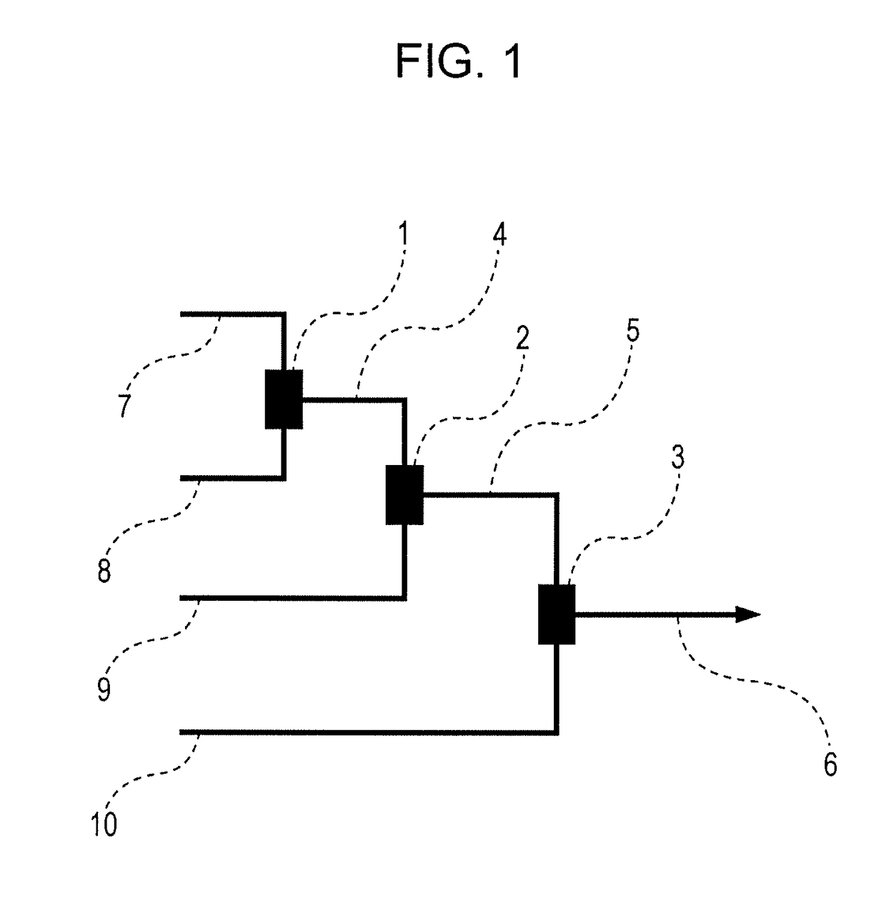
[0232]n-Butyllithium (BuLi) used as a polymerization initiator and styrene (St) used as a first monomer were introduced into the T-micromixer M1 illustrated in FIG. 1 from the tube reactors P1 and P2 illustrated in FIG. 1, respectively, and reacted with each other by living anionic polymerization to form a polymer.

[0233]The polymer was transferred into the T-micromixer M2 illustrated in FIG. 1 through the tube reactor R1 illustrated in FIG. 1. Subsequently, the growing ends of the polymer were trapped with a reaction controlling agent (i.e., 1,1-diphenylethylene (DPE)) introduced from the tube reactor P3 illustrated in FIG. 1.

[0234]Then, methacrylic acid tert-butyl ester (t-BMA) used as a second monomer was introduced into the T-micromixer M3 from the tube reactor P4 illustrated in FIG. 1 and reacted with the polymer transferred through the tube reactor R2 illustrated in FIG. 1 by continuous living anionic polymerization. Subsequently, the reaction was quenched ...

synthesis example 2

[0239]BuLi used as a polymerization initiator and St used as a first monomer were introduced into the T-micromixer M1 illustrated in FIG. 1 from the tube reactors P1 and P2 illustrated in FIG. 1, respectively, and reacted with each other by living anionic polymerization to form a polymer.

[0240]The polymer was transferred into the T-micromixer M2 illustrated in FIG. 1 through the tube reactor R1 illustrated in FIG. 1. Subsequently, the growing ends of the polymer were trapped with a reaction controlling agent (i.e., α-methylstyrene (α-MeSt)) introduced from the tube reactor P3 illustrated in FIG. 1.

[0241]Then, t-BMA used as a second monomer was introduced into the T-micromixer M3 from the tube reactor P4 illustrated in FIG. 1 and reacted with the polymer transferred through the tube reactor R2 illustrated in FIG. 1 by continuous living anionic polymerization. Subsequently, the reaction was quenched with methanol. Hereby, a block copolymer (PA-2) was produced.

[0242]In the above reacti...

synthesis example 3

[0245]A polymer (P-3) was produced as in Synthesis example 1, except that the types of monomers used, the amount of monomers used, and the like were changed.


PUM

PropertyMeasurementUnit
acid valueaaaaaaaaaa
particle sizeaaaaaaaaaa

Abstract

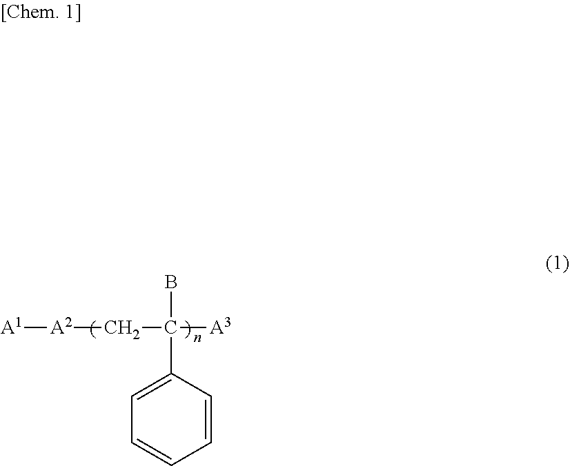
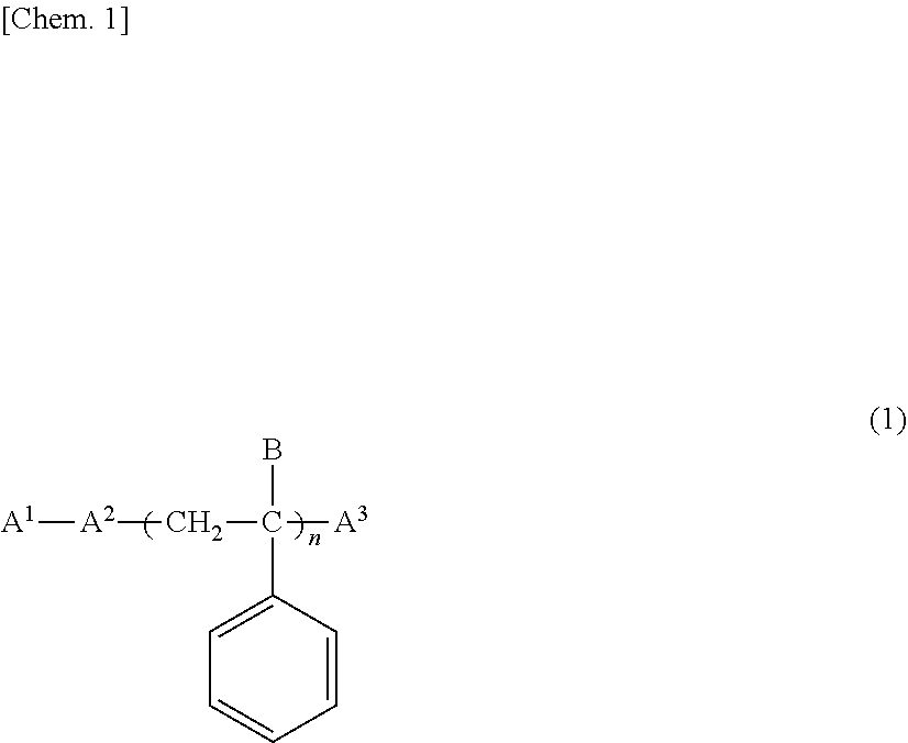
Provided is a printing agent including a pigment, a pigment dispersant, water, an organic solvent, and a binder resin, the pigment dispersant being a polymer (A) including an anionic group, the polymer (A) having a solubility in water of 0.1 g / 100 ml or less, a number-average molecular weight of 1000 to 6000, and an acid value of 40 to 400 mgKOH / g. Also provided is a printed fabric produced by applying the printing agent on a fabric. The polymer (A) is preferably a polymer represented by General Formula (1) (where A1 represents a residue of an organolithium initiator; A2 represents a polymer block including a monomer having an aromatic ring or a heterocyclic ring; A3 represents a polymer block including an anionic group; n represents an integer of 1 to 5; and B represents an aromatic group or an alkyl group).

Description

TECHNICAL FIELD[0001]The present invention relates to a printing agent and a printed fabric produced by applying the printing agent to a fabric.BACKGROUND ART[0002]One of the known methods for printing an image, such as a character, a drawing, or a pattern, on a fabric, such as a woven fabric, a nonwoven fabric, or a knitted fabric, is pigment printing in which an aqueous pigment ink is used. Pigment printing is a method in which a printing agent that is a pigment composition including a color pigment and a binder resin is applied to a base material and, after a dry-curing step has been conducted as needed, the printing agent is fixed to the base material. Known examples of the above printing method include silk screen printing (e.g., see PTL 1) in which a pattern formed on a screen fabric is sequentially printed on a fabric; and ink jet recording (e.g., see PTL 2) in which an ink ejected from a nozzle is deposited on a fabric.[0003]For preparing a printing agent, commonly, an aqueo...

Claims


Application Information

Patent Timeline
Patent Type & Authority Applications(United States)
IPC IPC(8): D06P1/52D06P1/14
CPCD06P1/525D06P1/5285D06P1/14D06P1/44D06P5/00D06P5/30D06P1/5221D06P1/5242D06P1/5271B01J19/0093C08F8/12C09D11/106C09D11/322C09D11/326B01J2219/00889C08F297/02C08L53/00C08L53/005
Inventor KIDO, TOMOKOUEMURA, YUKIEKIMURA, TOSHIHISATANAKA, HISAKAZUOJI, YASUOOE, NOBUHIRO
Owner DAINIPPON INK & CHEM INC
Learn More