Distributed wireless communication system for moving vehicles

a wireless communication and moving vehicle technology, applied in the direction of wireless commuication services, network data management, assess restriction, etc., can solve the problems of introducing several potential sources of communication performance degradation, difficult to obtain direct communication between terminal antennas within the carriage and externally located antennas, etc., to achieve simple and efficient distributed communication system, reduce the number of modems in the system, and high bandwidth

Active Publication Date: 2018-01-18
ECOMELA
View PDF9 Cites 9 Cited by
  • Summary
  • Abstract
  • Description
  • Claims
  • Application Information

AI Technical Summary

Benefits of technology

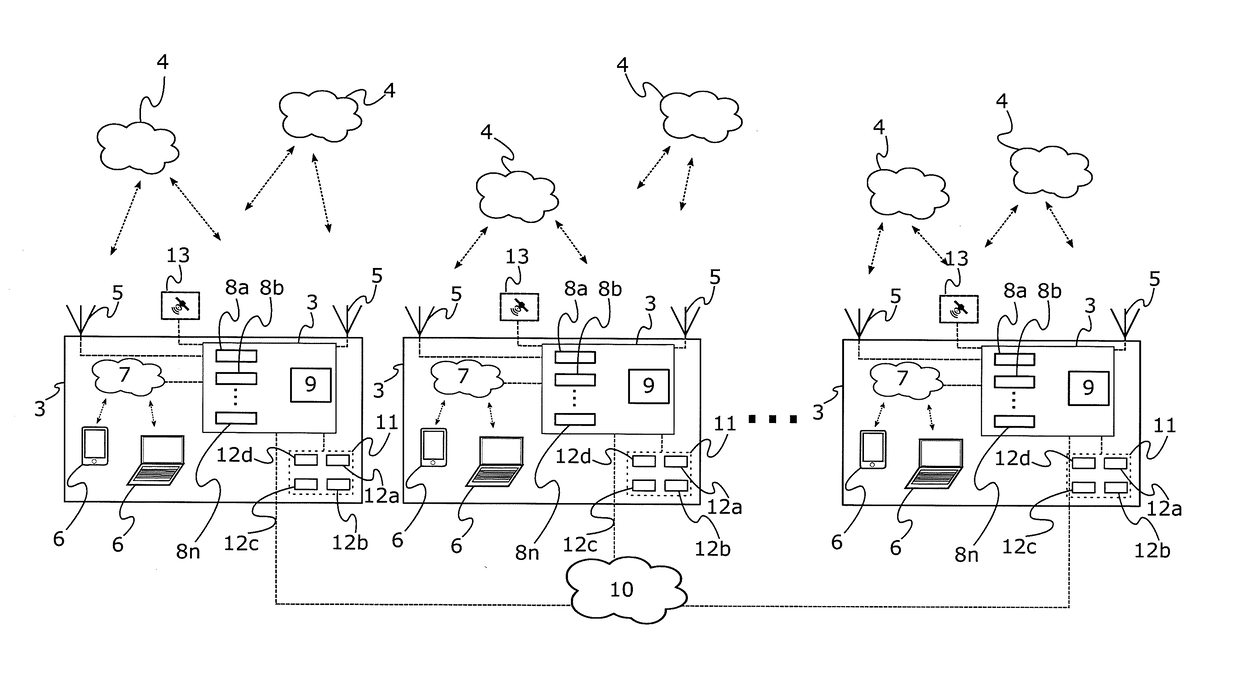
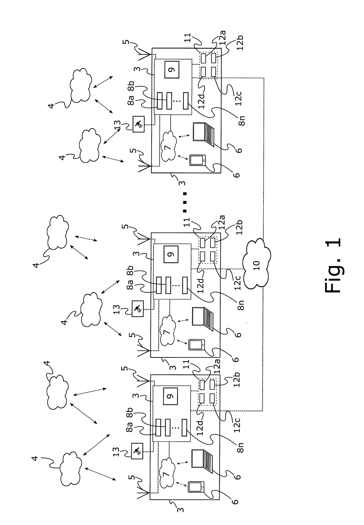
[0031]Thus, the inventors realized that by having a distributed communication system, i.e. a plurality of routers positioned in different separate carriages instead of one single centrally positioned router, many advantageous effects can be achieved. The distributed routers are completely standalone and independent, thus there is no main or master router, but rather “peer routers”. Moreover, by configuring the routers to be able to communicate with each other through an onboard router network data streams can efficiently be distributed among the plurality of routers and the corresponding exterior network connections. Thus, each router can “borrow” bandwidth capacity from any one of the other routers onboard the vehicle. This results in a superior communication system in terms of capacity and bandwidth capability. Moreover, the communication system is more robust as compared to conventional systems. For example, if one router would temporarily not be able to communicate with an exterior mobile network due to e.g. software / hardware malfunction, poor network coverage, signal obstruction, etc., the data packets received from and sent to clients can instead be routed to other routers onboard the vehicle. Also, since each router is standalone and independent the communication system is less dependent on one single router.
[0032]In accordance with another exemplary embodiment, each router comprises a plurality of modems for communication with the at least one exterior mobile network, wherein each modem is connectable to at least two external antennas in order to enable MIMO communication. Thus, the router may comprise several antenna ports per modem, enabling MIMO for the external communication, and the high bandwidth thereby provided can then be distributed to the internal clients with e.g. 802.11n. The modems comprised by each router may share a plurality of antennas, i.e. there may be for example two or four antennas arranged on the roof of a carriage which can only be utilized by one modem at the time. Alternatively a carriage having a router may have two or more antenna configurations, each antenna configuration including a plurality of antennas distributed on the exterior of the carriage, and where each configuration is simultaneously usable by two or more modems.
[0033]For example, a carriage may have two antennas at a front end portion and two antennas at a rear end portion of the roof which can either define one side of one 4×4 MIMO system or one side of two 2×2 MIMO systems. Where, one side of a MIMO system is to be understood as that the moving vehicle being “a side” and a base station of an exterior mobile network is “the other side”.
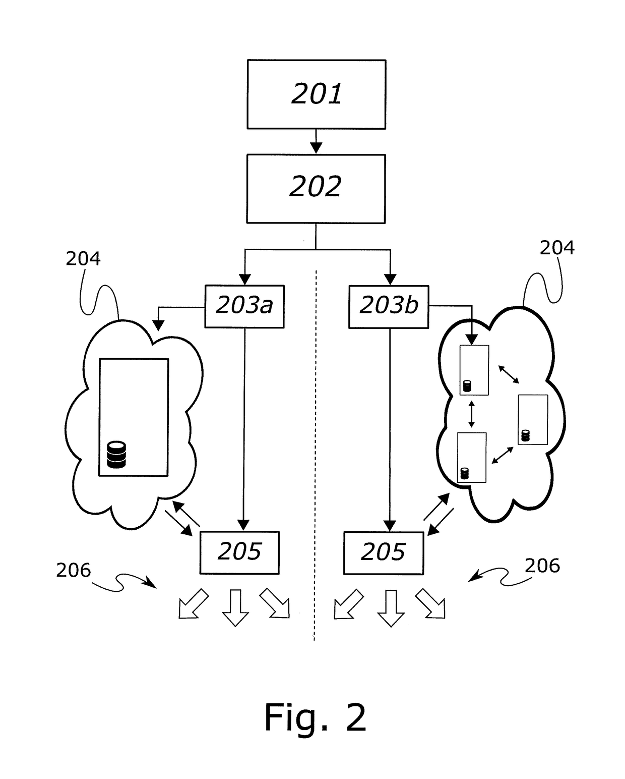
[0034]According to yet another exemplary embodiment the wireless communication system further comprises a distributed database including at least one of available bandwidth of each data link of each router, a current mobile network operator of each router, a set of signal parameters for each data link of each router, a network topology of the onboard router network, a number of routers in the onboard router network and an IP-address of each router in the onboard router network. By providing a database in the system comprising certain parameters that are accessible by each router or each controller a simple and efficient distributed communication system can be realized. The distributed database can be a plurality of databases, e.g. one for each router connected to the onboard router network. The distributed database(s) can then be kept continuously synchronized between the different routers connected to the onboard router network in order to ensure that each router has access to the same information at all times. The distributed database may further include the network topology of the routers onboard the vehicle, i.e. how they are connected to each other and if for example packets from a first router must pass through a second router in order to reach a third router, or if there is a direct communication path from the first to the third router, and so on. The controller(s) may then, in accordance with another exemplary embodiment, also be configured to retrieve information from the distributed database and assign data streams at least partly based on the retrieved information.
[0035]Further, in accordance with yet another exemplary embodiment, each router of the plurality of routers is associated with a different mobile network operator. Thus, if a specific network operator has poor network coverage in certain areas, other routers within the same moving vehicle having other network operators with better network coverage can be used to handle some of the data traffic.
[0036]Moreover, each router may further comprise a subscriber identity module (SIM) pool including a plurality of SIMs, and wherein the controller is capable of periodically assigning SIMs within the SIM pool to any one of the plurality of routers through the onboard router network. By including a SIM pooling capability in the system the number SIM cards (SIMs) and also the number of modems in the system can be reduced. By using a common pool of SIMs, accessible to each of the plurality of routers, the total number of SIMs may be reduced, and the SIMs available may be used more efficiently. At the same time, the accessibility for each router (or the modems within each router) to an adequate SIM at each time increases since the number of accessible SIMs can hereby be managed more efficiently.

Problems solved by technology

Thus, train carriages are often shielded compartments, and direct communication between terminal antennas within the carriages and externally located antennas is difficult to obtain.
Further, in regards to recent developments in the field of smartphones, and the way these are commonly used, with e.g. continuously operating applications, many smartphones are active at all times, meaning that many handovers are required when the train moves.
Even though this problem is common for all moving vehicles, it is especially pronounced for vehicles moving at high speed, such as trains.
The mobile nature of a client with respect to the base stations may also introduce several potential sources of communication performance degradation.
Such sources may derive from complex terrain, competition for available channels, or the source may be an unknown source of noise related to e.g. radio-frequency interference.
However, this solution may still be insufficient to obtain an optimal transmission performance, especially for large data volumes.
Trains and other moving vehicles often pass through areas with bad radio coverage, and moreover, present solutions are often unable to properly handle the large amount of traffic.
Further, in the light of recent developments regarding wireless communication methods and systems, such as e.g. developments relating to MIMO (multiple-input multiple-output) technology, presently known wireless communication systems for trains are becoming more and more out-dated.
Thus, current systems are unable to make efficient use and benefit of the developments made in new telecom techniques, such as MIMO, and are often even incapable of integrating such techniques at all.
Yet further, MIMO systems aside, the practical limitations caused by the limited amount of space on the roof of a train carriage is forming a bottle-neck for the bandwidth capacity for the onboard communication system.
Even though the above discussion is focused on trains, similar situations and problems are at least to some extent encountered in other types of moving multi-carriage vehicles, such as trams.

Method used


Image

  • Distributed wireless communication system for moving vehicles
  • Distributed wireless communication system for moving vehicles
  • Distributed wireless communication system for moving vehicles

Examples


Embodiment Construction

[0068]In the following detailed description, preferred embodiments of the present invention will be described. However, it is to be understood that features of the different embodiments are exchangeable between the embodiments and may be combined in different ways, unless anything else is specifically indicated. Even though in the following description, numerous specific details are set forth to provide a more thorough understanding of the present invention, it will be apparent to one skilled in the art that the present invention may be practiced without these specific details. In other instances, well known constructions or functions are not described in detail, so as not to obscure the present invention. In the following examples, an embodiment related to a train is disclosed. However, it is to be acknowledged by the skilled reader that the method and system are correspondingly useable on other moving vehicles having a plurality of carriages, such as trams and the like.

[0069]FIG. ...


PUM


Abstract

A wireless communication system and method for a moving vehicle having a plurality of carriages is disclosed. The system includes a plurality of routers, each router being arranged in a separate carriage and each router being configured to receive and transmit wireless data communication to and from a stationary communication server outside said moving vehicle through at least one exterior mobile network via at least one antenna, wherein said at least one exterior mobile network provides at least one data link; receive and transmit data packets to and from at least one client onboard the moving vehicle; and communicate with every other router in said moving vehicle in order to receive and transmit data packets to and from said every other router, thereby forming an onboard router network.

Description

TECHNICAL FIELD OF THE INVENTION[0001]The present invention relates to a wireless communication system for moving vehicles, such as trains.BACKGROUND[0002]The demands on wireless communication capabilities in today's society are increasing rapidly. In particular, there is an increasing demand from passengers to be able to communicate through mobile phones and other handheld devices when traveling. Furthermore, there is also a rapidly growing demand to be able to get access to the Internet with laptops, PDAs, smartphones, and the like when traveling, for example, by train. However, train carriages are made of metal, and even the windows are normally covered with a thin metal film. Thus, train carriages are often shielded compartments, and direct communication between terminal antennas within the carriages and externally located antennas is difficult to obtain. Further, in regards to recent developments in the field of smartphones, and the way these are commonly used, with e.g. contin...

Claims


Application Information

Patent Timeline
Patent Type & Authority Applications(United States)
IPC IPC(8): H04W4/04H04L12/24H04W8/26H04W40/12H04W84/00
CPCH04W4/046H04W40/12H04L41/0806H04W84/005H04L41/12H04W8/26H04B7/0413H04W8/183H04W48/18H04W4/029H04W4/46H01Q21/29H04B1/3822H04W40/24H04W4/42H04W4/48
Inventor KARLSSON, MATSEKLUND, PETER
Owner ECOMELA
Why Eureka
Try Eureka