Toner, toner accommodating unit, and image forming apparatus

a toner and forming apparatus technology, applied in the field of toner, can solve the problems of high fixing energy required, disadvantageous presence of much of the wax on the toner surface, and insufficient output image quality, and achieve the effects of high glossiness, high fixing energy, and excellent low temperature fixing ability

Active Publication Date: 2018-01-25
RICOH KK
View PDF5 Cites 3 Cited by
  • Summary
  • Abstract
  • Description
  • Claims
  • Application Information

AI Technical Summary

Benefits of technology

[0025]According to the present invention, it is possible to solve the above problems pertinent in the art, and to provide a toner that does not cause filming, and that is excellent in low temperature fixing ability, hot offset resistance, high glossiness, high color reproducibility, and heat resistant storage stability.

Problems solved by technology

In particular, improvement in low temperature fixing ability is very important because power consumption in fixing occupies much of power consumption in an image forming step.
In the toners produced by the kneading pulverizing method, is difficulty encountered in making them have smaller particle diameters, and their shapes are indefinite and their particle size distribution is broad, for which these toners have the following problems, for example: the quality of output images is not sufficient; and the fixing energy required is high.
Also, when wax (release agent) has been added for improving fixing ability, the toners produced by the kneading pulverizing method are cracked at the interfaces with the wax upon pulverization, so that much of the wax is disadvantageously present on the toner surface.
Thus, their entire performances have not been satisfactory, which is problematic.
These proposed techniques, however, do not attain high-level low temperature fixing ability that has been demanded recently.
As a result, when both the crystalline polyester resin and the non-crystalline polyester resin melt to some extent, the resultant toner is not fixed.
Therefore, these proposed techniques do not satisfy high-level low temperature fixing ability, which has been highly demanded recently.
According to this technique, however, the three-dimensional network structure is obtained through an ester reaction of diol, dicarboxylic acid, a polyhydric alcohol, or an acid, and the polyhydric alcohol or the acid to be a branched structure ununiformly exists.
The loose portion may lead to deterioration in heat resistant storage stability, and the tight portion may lead to deterioration in low temperature fixing ability, image glossiness, image density, and color reproducibility.
Therefore, without the network structure densely formed, heat resistant storage stability may be difficult to retain, and sufficient low temperature fixing ability and image glossiness cannot be obtained.
Accordingly, the resultant toner does not satisfy high-level low temperature fixing ability or image quality, although these have been recently demanded.

Method used


Image

  • Toner, toner accommodating unit, and image forming apparatus
  • Toner, toner accommodating unit, and image forming apparatus
  • Toner, toner accommodating unit, and image forming apparatus

Examples


production example 1

[0435]

[0436]A reaction container equipped with a stiffing rod and a thermometer was charged with isophorone diisocyanate (170 parts) and methyl ethyl ketone (75 parts), followed by reaction at 50° C. for 5 hours, to thereby obtain [ketimine compound 1].

[0437]The amine value of the obtained [ketimine compound 1] was found to be 418.

production example a-1

[0438]

[0439]Synthesis of Prepolymer A-1

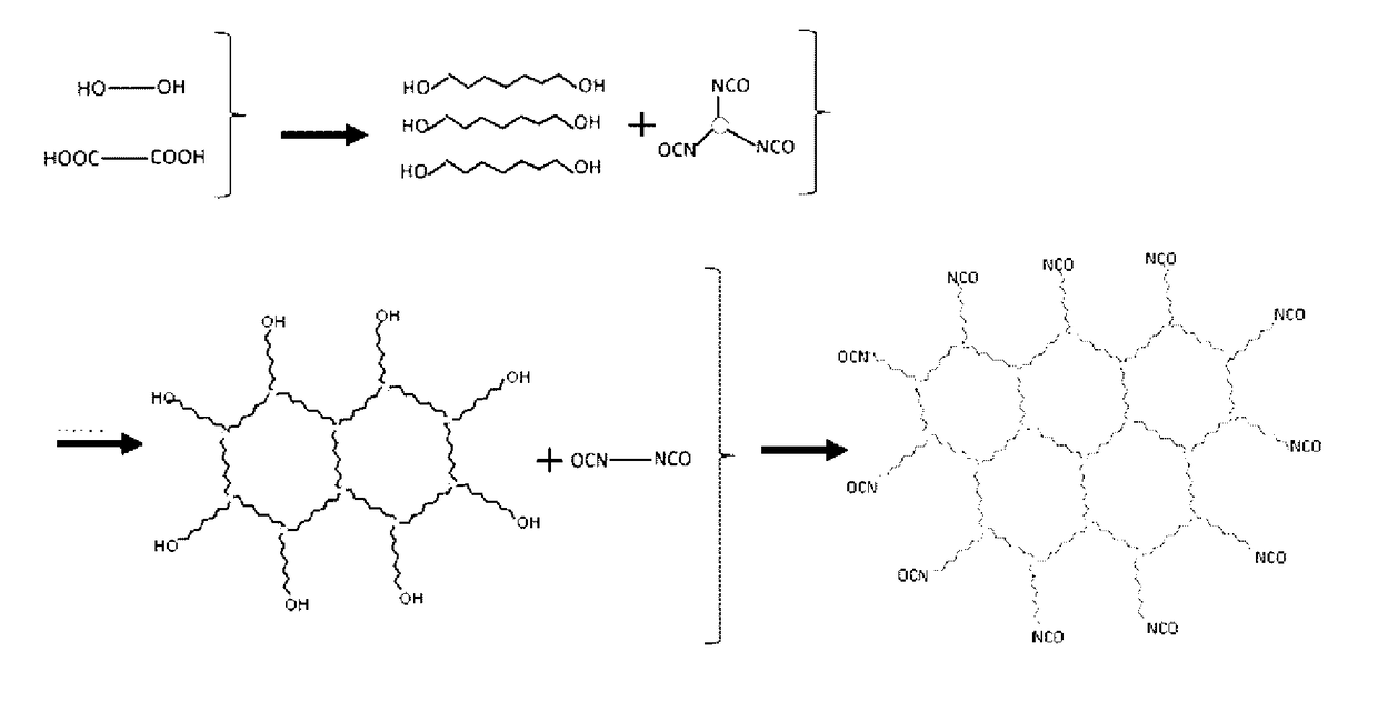
[0440]A reaction vessel equipped with a condenser, a stiffing device, and a nitrogen-introducing tube was charged with 3-methyl-1,5-pentanediol, terephthalic acid, and adipic acid so that a ratio by mole of hydroxyl group to carboxyl group “OH / COOH” was 1.2. A diol component was composed of 100 mol % of 3-methyl-1,5-pentanediol, and a dicarboxylic acid component was composed of 50 mol % of terephthalic acid and 50 mol % of adipic acid. Moreover, titanium tetraisopropoxide (1,000 ppm relative to the resin component) was added thereto.

[0441]Thereafter, the resultant mixture was heated to 200° C. for about 4 hours, then was heated to 230° C. for 2 hours, and was allowed to react until no flowing water was formed.

[0442]Thereafter, the reaction mixture was allowed to further react for 5 hours under a reduced pressure of 10 mmHg to 15 mmHg, to thereby obtain intermediate polyester A′-1.

[0443]The obtained intermediate polyester A′-1 was found to have ...

production example a-2

[0451]

[0452]Synthesis of Prepolymer A-2

[0453]A reaction vessel equipped with a condenser, a stirring device, and a nitrogen-introducing tube was charged with 3-methyl-1,5-pentanediol, terephthalic acid, and adipic acid so that a ratio by mole of hydroxyl group to carboxyl group “OH / COOH” was 1.2. A diol component was composed of 100 mol % of 3-methyl-1,5-pentanediol, and a dicarboxylic acid component was composed of 50 mol % of terephthalic acid and 50 mol % of adipic acid. Moreover, titanium tetraisopropoxide (1,000 ppm relative to the resin component) was added thereto.

[0454]Thereafter, the resultant mixture was heated to 200° C. for about 4 hours, then was heated to 230° C. for 2 hours, and was allowed to react until no flowing water was formed.

[0455]Thereafter, the reaction mixture was allowed to further react for 5 hours under a reduced pressure of 10 mmHg to 15 mmHg, to thereby obtain intermediate polyester A′-2.

[0456]The obtained intermediate polyester A′-2 was found to have ...


PUM

PropertyMeasurementUnit
glass transition temperatureaaaaaaaaaa

Abstract

A toner, including: a polyester resin, wherein the polyester resin has a structure represented by any one of formulas 1) to 3) below: 1) R1-(NHCONH-R2)n-, 2) R1-(NHCOO-R2)n-, and 3) R1-(OCONH-R2)n-, where n is 3 or more, R1 represents an aromatic organic group or an aliphatic organic group, and R2 represents a group derived from a resin that is polyester formed of polycarboxylic acid, polyol, or both thereof; or that is a modified polyester obtained by modifying polyester with isocyanate.

Description

TECHNICAL FIELD[0001]The present invention relates to a toner, a toner accommodating unit, and an image forming apparatus.BACKGROUND ART[0002]In recent years, toners have been required to have smaller particle diameters and hot offset resistance for increasing quality of output images, to have low temperature fixing ability for energy saving, and to have heat resistant storage stability for the toners to be resistant to high-temperature, high-humidity conditions during storage and transportation after production. In particular, improvement in low temperature fixing ability is very important because power consumption in fixing occupies much of power consumption in an image forming step.[0003]Conventionally, toners produced by the kneading pulverizing method have been used. In the toners produced by the kneading pulverizing method, is difficulty encountered in making them have smaller particle diameters, and their shapes are indefinite and their particle size distribution is broad, fo...

Claims


Application Information

Patent Timeline
Patent Type & Authority Applications(United States)
IPC IPC(8): G03G9/087
CPCG03G9/08755G03G9/08797G03G9/08764G03G9/08795G03G9/08793
Inventor SUGIMOTO, TSUYOSHINAKAYAMA, SHINYAYAMADA, HIROSHISANTO, HIDEYUKICHIBA, RYUTAAMEMORI, SUZUKANAGATA, KOHSUKE
Owner RICOH KK
Why Eureka
Try Eureka