
Memory controller, semiconductor memory system and operating method thereof

a memory controller and memory technology, applied in the direction of coding, instruments, code conversion, etc., can solve the problems of increasing read failure rate, reducing reliability, and device losing stored data, and achieve the effect of quick read

Active Publication Date: 2018-02-15
SK HYNIX INC +1
View PDF6 Cites 9 Cited by
  • Summary
  • Abstract
  • Description
  • Claims
  • Application Information

AI Technical Summary

Benefits of technology

The present invention is about a memory controller, semiconductor memory system, and operating method that can quickly and reliably read data stored in a highly-integrated semiconductor memory device. This technology allows for faster read times, improving the overall performance of the memory device.

Problems solved by technology

Volatile memory devices lose their stored data when their power supplies are interrupted, whereas non-volatile memory devices retain their stored data even when their power supplies are interrupted.
However, as the number of bits programmed in each memory cell increases, the reliability decreases and the read failure rate increases.
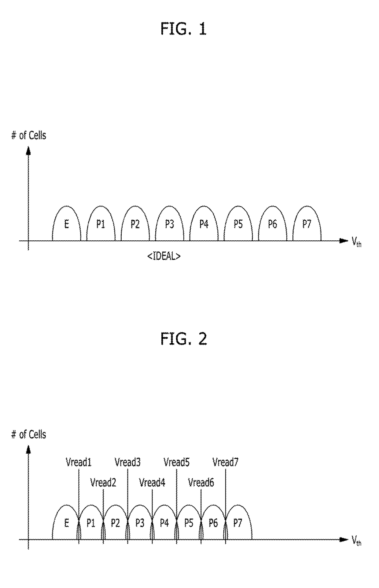
However, a voltage window available for the various threshold voltage distributions is finite.
Such charge loss may accelerate when the tunnel oxide film deteriorates because of iterative program and erase operations.
Charge losses may result in a decrease in the threshold voltages of memory cells.
Further, program disturbances, erase disturbances and / or back pattern dependencies may cause increases in the threshold voltages.
Once neighbouring threshold voltage distributions overlap, read data may include a significant number of errors when a particular read voltage is applied to a selected word line.
However, when neighbouring threshold voltage distributions overlap, a memory cell that has the third program state ‘P3’ may be erroneously determined to have the second program state ‘P2’.
In short, when the neighbouring threshold voltage distributions overlap as illustrated in FIG. 2, read data may include a significant number of errors.

Method used


Image

  • Memory controller, semiconductor memory system and operating method thereof
  • Memory controller, semiconductor memory system and operating method thereof
  • Memory controller, semiconductor memory system and operating method thereof

Examples


Embodiment Construction

[0075]Various embodiments will be described below in more detail with reference to the accompanying drawings. The present invention may, however, be embodied in different forms and should not be construed as limited to the embodiments set forth herein. Rather, these embodiments are provided so that this disclosure will be thorough and complete and will fully convey the present invention to those skilled in the art. The scope of the present invention will be understood through the claims of the present invention.

[0076]It is noted that the drawings are not necessarily to scale and, in some instances, proportions may have been exaggerated in order to more clearly illustrate the various elements of the embodiments.

[0077]Also, in the following description, numerous specific details are set forth in order to provide a thorough understanding of the present invention. The present invention may be practiced without some or ail of these specific details. In other instances, well-known process...


PUM


Abstract

An operation method of a memory controller includes: reading a second data from memory cells when a hard decision error correction decoding operation based on a first data read from the memory cells fails; calculating a LLR of each bit-data included in the first data by using the first and second data; and performing a soft decision error correction decoding operation based on the LLR, wherein the memory cells include a first and second memory cell, wherein the first data includes first-bit-data read from the first and second memory cell, wherein the second data includes second-bit-data read from the first and second memory cell, wherein the LLR is a LLR of the first-bit-data read from the first memory cell calculated based on the first bit and a second bit read from the first memory cell and a first bit and a second bit read from the second memory cell.

Description

CROSS-REFERENCE TO RELATED APPLICATIONS[0001]The present application claims priority of Korean Patent Application. No, 10-2016-0102985, filed on Aug. 12, 2016, which is incorporated herein by reference in its entirety.BACKGROUND1. Field[0002]Various exemplary embodiments of the present invention relate to a memory controller, a semiconductor memory system and an operating method thereof.2. Description of the Related Art[0003]In general, semiconductor memory devices are classified into volatile memory devices, such as Dynamic Random Access Memory (DRAM) and Static RAM (SRAM), and non-volatile memory devices, such as Read Only Memory (ROM), Mask ROM (MROM), Programmable ROM (PROM), Erasable PROM (EPROM), Electrically EPROM (EEPROM), Ferromagnetic RAM (FRAM), Phase change RAM (PRAM), Magnetic RAM (MRAM), Resistive RAM (RRAM) and flash memory.[0004]Volatile memory devices lose their stored data when their power supplies are interrupted, whereas non-volatile memory devices retain their s...

Claims


Application Information

Patent Timeline
IPC IPC(8): H03M13/11G06F11/10H03M13/37H03M13/29H03M13/00
CPCH03M13/1105H03M13/1171H03M13/2957G06F11/10H03M13/3707H03M13/116H03M13/6343G06F11/1012H03M13/1108H03M13/1111H03M13/3715H03M13/3738H03M13/3746H03M13/45G11C16/26G11C11/5642G06F11/1048G06F11/1068G11C2211/5621
Inventor HA, JEONG-SEOKLEE, SANG-HAKIM, DAE-SUNG
Owner SK HYNIX INC
Learn More