
Electric power adjustment system and control method for electric power adjustment system

Active Publication Date: 2018-02-22
NISSAN MOTOR CO LTD
View PDF14 Cites 8 Cited by
  • Summary
  • Abstract
  • Description
  • Claims
  • Application Information

AI Technical Summary

Benefits of technology

The patent text suggests using a large capacity condenser to smooth the output voltage of a fuel cell and reduce the ripple current component. However, this solution increases manufacturing costs. The technical effect of this patent is to reduce the cost of manufacturing an electric power adjustment system that includes a fuel cell while still achieving a smoother output voltage.

Problems solved by technology

However, such large capacity condenser is expensive.
Therefore, disposing the large capacity condenser for smoothing voltage has a problem of increasing a manufacturing cost of the electric power adjustment system including the fuel cell.
In this case, there is also a problem that the internal impedance of the fuel cell cannot be accurately calculated.
Depending on a case, there is also a problem that the internal impedance of the fuel cell cannot be normally detected due to a detection value of an impedance detector (an impedance detection circuit) being saturated.

Method used


Image

  • Electric power adjustment system and control method for electric power adjustment system
  • Electric power adjustment system and control method for electric power adjustment system
  • Electric power adjustment system and control method for electric power adjustment system

Examples


first embodiment

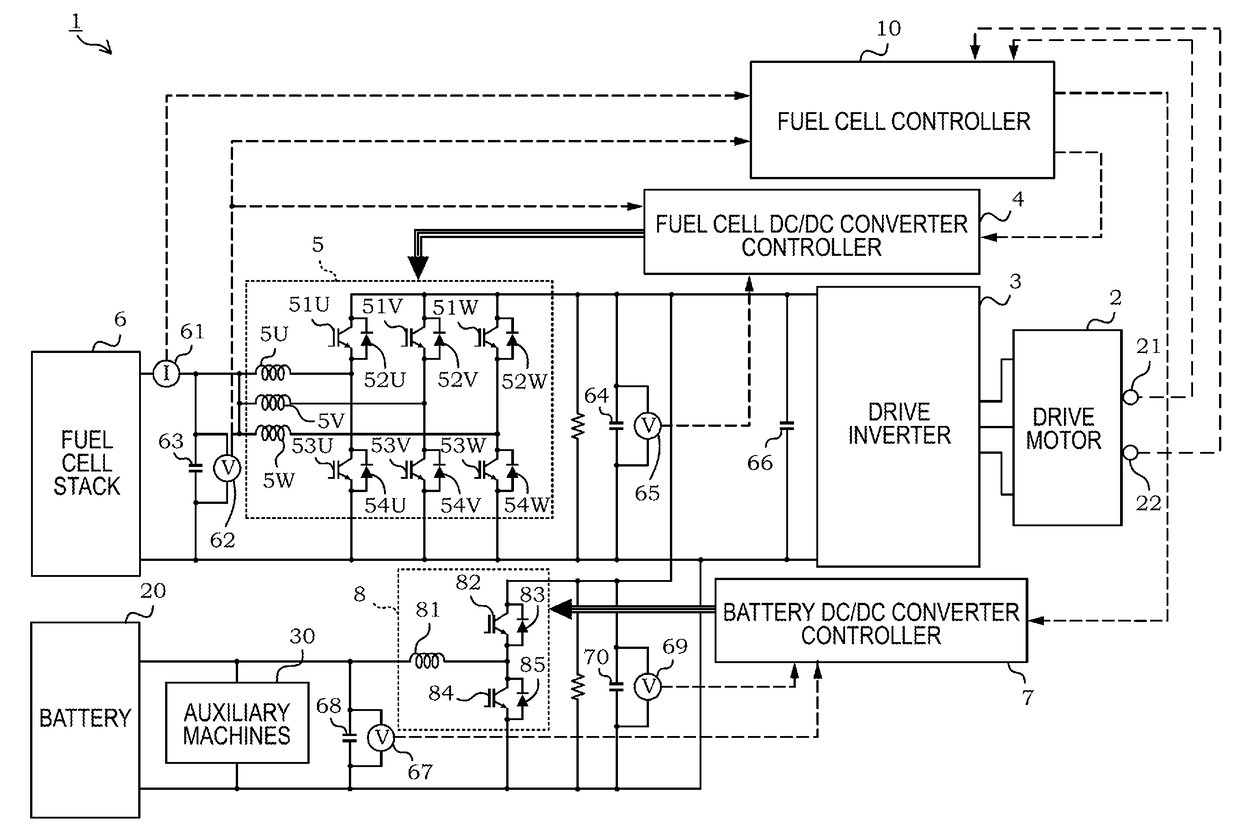
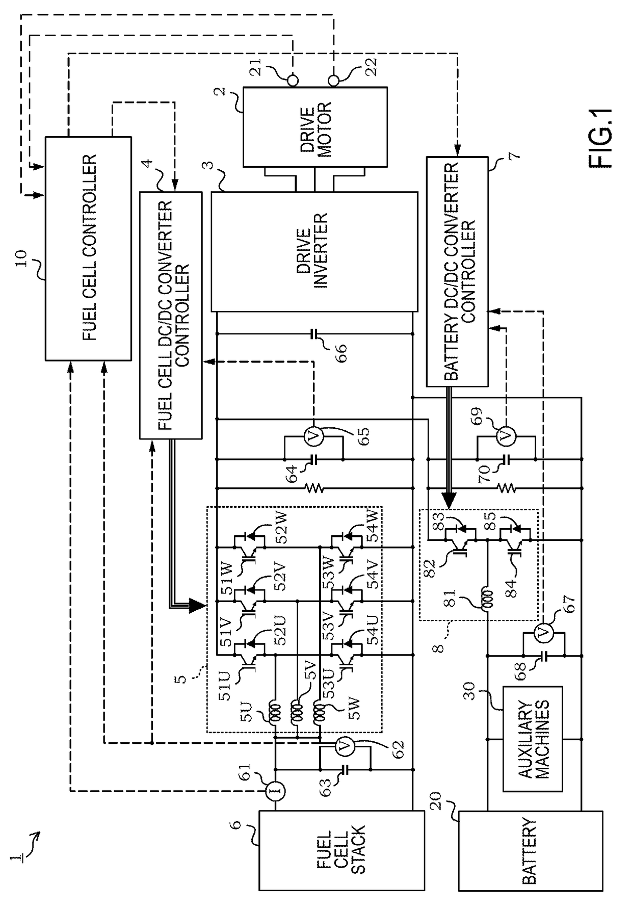
[0033]FIG. 1 is a drawing illustrating an overall configuration of an electric power adjustment system 1 for a fuel cell (hereinafter simply referred to as the “electric power adjustment system 1”) according to a first embodiment of the present invention. The electric power adjustment system 1 of the present invention is one that is used for a vehicle that at least uses the fuel cell as a driving source. This electric power adjustment system 1 is mounted on, for example, an electric vehicle that drives the vehicle using a drive motor 2 as illustrated in FIG. 1. It should be noted that this electric power adjustment system 1 is applicable to a load in, for example, a device other than a fuel cell vehicle (an electric vehicle using the fuel cell) as long as the device uses the fuel cell as the driving source.

[0034]As illustrated in FIG. 1, the electric power adjustment system 1 of this embodiment includes a fuel cell stack 6, a DC / DC converter 5 for the fuel cell stack 6, a high-volta...

second embodiment

[0176]The following describes a second embodiment of the present invention, mainly differences from the first embodiment. It should be noted that the overall configuration of the electric power adjustment system 1 is, since being similar, described by referring to FIG. 1, but a functional configuration of a fuel cell controller 10 is described by referring to FIG. 13.

[0177]In the above-described first embodiment, the number of drive phases of the multi-phase converter 5 is switched on the basis of the required voltage ratio of the multi-phase converter 5 and the DC link voltage is specified to any one of the output voltage from the fuel cell stack 6 or the motor lower limit voltage of the drive motor 2. In this embodiment, the generation of the ripple current component is optimally restrained by appropriately adjusting a required voltage value of the DC link voltage without switching the number of drive phases of the multi-phase converter 5.

[0178]FIG. 13 is a block diagram illustrat...

third embodiment

[0201]The following describes a third embodiment of the present invention, mainly differences from the first embodiment and the second embodiment. It should be noted that the overall configuration of the electric power adjustment system 1 is, since being similar, described by referring to FIG. 1, but a functional configuration of a fuel cell controller 10 is described by referring to FIG. 17.

[0202]In the above-described first embodiment, the number of drive phases of the multi-phase converter 5 is switched and the DC link voltage is specified as any one of the output voltage from the fuel cell stack 6 or the motor lower limit voltage of the drive motor 2. In the above-described second embodiment, the required voltage value of the DC link voltage is appropriately adjusted without switching the number of drive phases of the multi-phase converter 5. In this embodiment, a description will be given of the case where these two controls are simultaneously performed.

[0203]FIG. 17 is a block...


PUM


Abstract

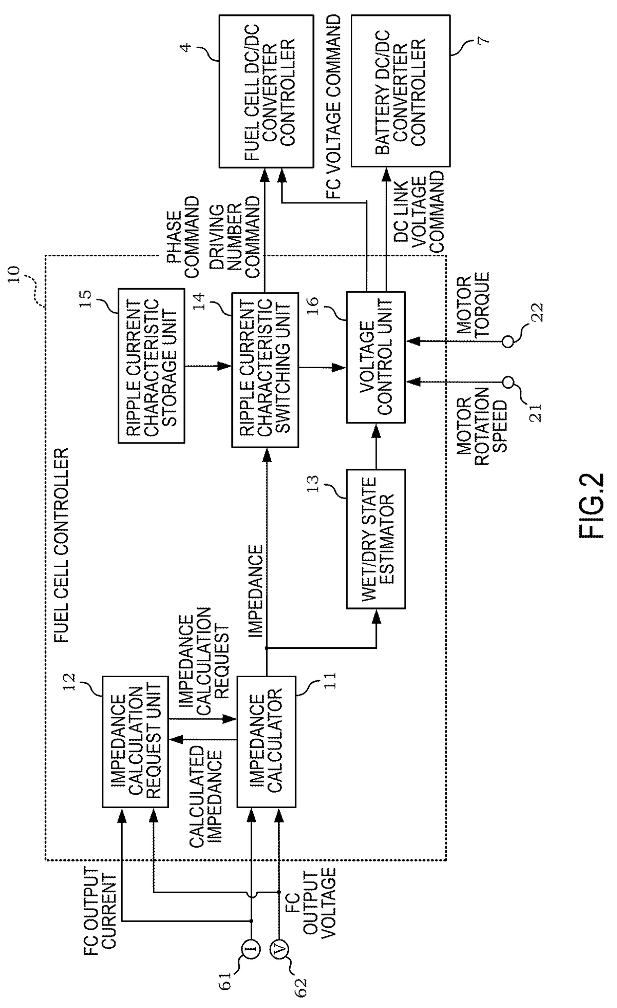
An electric power adjustment system includes a fuel cell connected to a load, and a multi-phase converter connected between the fuel cell and the load. The multi-phase converter is constituted of a plurality of phases and converts an output voltage from the fuel cell by a predetermined required voltage ratio. The electric power adjustment system includes a ripple current characteristic switching unit configured to switch a ripple current characteristic with respect to an input current to the multi-phase converter by changing at least one of a drive phase number and the voltage ratio of the multi-phase converter according to an operation state of the fuel cell and a required electric power of the load.

Description

TECHNICAL FIELD[0001]The present invention relates to an electric power adjustment system that switches ripple current characteristics by switching at least one of the number of drive phases and a voltage ratio of a multi-phase converter and a control method for the electric power adjustment system.BACKGROUND ART[0002]Among electric power adjustment systems that include a fuel cell, there is known an electric power adjustment system that is configured to supply an output power of the fuel cell to a load by supplying a fuel gas (such as hydrogen) and an oxidant gas (such as air) to the fuel cell in response to a request from the load that is connected to the fuel cell.[0003]In the electric power adjustment system as described above, in order to control an operation state of the fuel cell, a wet / dry state (a wetness degree) of the fuel cell is estimated on the basis of an alternating-current component in an output current and an output voltage from the fuel cell that has a correlation...

Claims


Application Information

Patent Timeline
IPC IPC(8): H02P27/08H01M8/04858B60L11/18
CPCH02P27/08H01M8/04865B60L11/1803B60L11/1887H01M2250/20B60L15/02H01M8/04537B60L2240/529B60L2270/14B60L2240/527H01M8/0488H01M16/006H01M8/04589H02M1/15B60L50/51B60L58/40Y02T10/64Y02T90/40Y02T10/70Y02T10/7072Y02T90/14Y02E60/50Y02E60/10B60L53/20B60L58/10B60L58/30H01M8/04634H01M8/04925H02M3/155H02M7/219B60L2240/423B60L2210/10B60Y2200/91
Inventor MATSUMOTO, MICHIHIKOYOSHIDA, HIDEOAOKI, TETSUYA
Owner NISSAN MOTOR CO LTD
Learn More