Integrated process for capturing carbon dioxide

a carbon dioxide and integrated technology, applied in the field of integrated process for capturing carbon dioxide, can solve the problems of increasing electricity costs by over 70% in some cases, and the implementation of these technologies, such as the chilled ammonia and monoethanolamine carbon capture process, has been limited to pilot plants, so as to reduce co2 emissions, increase electricity costs, and reduce operating and capital costs

Inactive Publication Date: 2017-09-21
SOLVCOR TECH LLC
View PDF4 Cites 9 Cited by
  • Summary
  • Abstract
  • Description
  • Claims
  • Application Information

AI Technical Summary

Benefits of technology

[0003]One promising means of reducing CO2 emissions is post-combustion CO2 capture and utilization (CCU), which transforms low concentrations of CO2 in emissions into high purity CO2 for utilization or disposal. However, implementation of these technologies, such as the chilled ammonia and monoethanolamine (MEA) carbon capture processes, has been limited to pilot plants due to enormous operating costs. The most effective current processes require high temperature heat, generally supplied by steam diverted from power generation, increasing electricity costs by over 70% in some cases. High temperature heat constitutes >80% of the energy consumption in current carbon capture processes and is the costliest component of CO2 capture. A significantly lower operating and capital cost CO2 capture system is necessary to make CCU an effective means of reducing CO2 emissions.

Problems solved by technology

However, implementation of these technologies, such as the chilled ammonia and monoethanolamine (MEA) carbon capture processes, has been limited to pilot plants due to enormous operating costs.
The most effective current processes require high temperature heat, generally supplied by steam diverted from power generation, increasing electricity costs by over 70% in some cases.
High temperature heat constitutes >80% of the energy consumption in current carbon capture processes and is the costliest component of CO2 capture.
Due to the cost prohibitive nature of current CO2 capture systems, over 80 percent of the demand for pure CO2 is supplied by the unsustainable drilling of CO2 source fields, which contain CO2 that has been sequestered for millions of years.

Method used


Image

  • Integrated process for capturing carbon dioxide
  • Integrated process for capturing carbon dioxide
  • Integrated process for capturing carbon dioxide

Examples


example 1

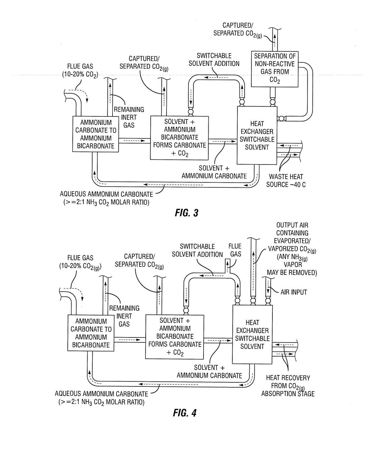
[0275]A water soluble substance is added at a moderate or cool temperature, such as at room temperature, in the CO2 desorption stage and gaseous CO2 is desorbed. After at least a significant portion, such as less than any of the following: 5%, or 10%, or 15%, or 20%, or 25%, or 30%, or 35%, or 40%, or 45%, or 50% of the CO2 in solution, is desorbed, heat may be applied to the mixed desorption solution in a separate or the same reactor or reactors. It may also be desirable for heat to be applied when the CO2 desorption rate due to the presence of the soluble substance has appreciably subsided, such as the CO2 desorption rate subsiding to less than any of the following: 95%, or 90%, or 75%, or 60%, or 50% or 40%, or 30%, or 20%, or 10% of the maximum CO2 desorption rate after soluble substance injection. The application of heat may enhance CO2(g) desorption. The temperature and energy requirements for thermal desorption may be significantly less than conventional thermal desorption pr...

example 2

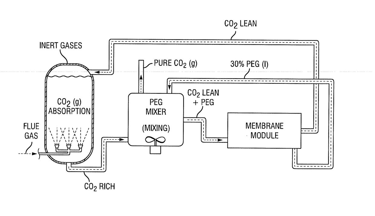
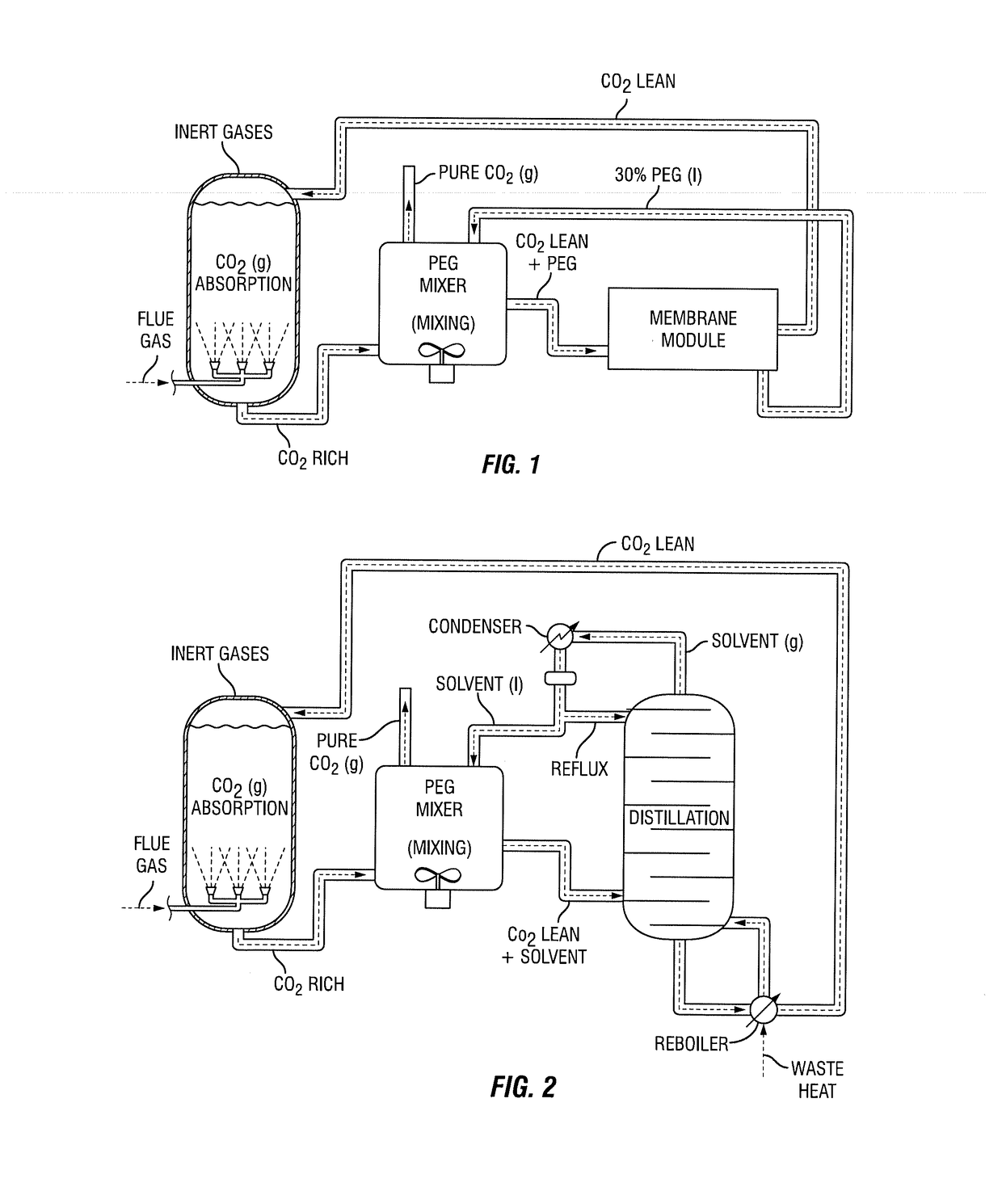
[0276]The water-soluble substance is added to the CO2-rich solution in the CO2 desorption stage and heat is applied to the solution during most the CO2 desorption timeframe. Depending on the concentration of the added substance, the rate and temperature of heat input, residence time, the rate of mixing and other factors, the initial CO2 desorption may be primarily due to the influence of the soluble substance. During this initial timeframe, the heat may, include, but not be limited to, increase the rate of CO2 desorption or facilitate CO2 desorption. Depending on many factors, the influence of heat application on CO2 desorption may increase over time and the influence of the added substance may subside. It may be desirable for the added substance in this example to be relatively non-volatile and not prone to substantial thermal degradation. Such substances, include, but are not limited to, PEGs and PPGs.

example 3

[0277]In embodiments where the added substance is recovered using heat, such as embodiments with various forms of distillation or switchable solvent, or where heat is applied during soluble substance recovery, such as may be the case in membrane-based recovery embodiments, CO2(g) may be desorbed. This CO2 desorption may be in part due to thermal decomposition. This CO2 may be recovered and utilized in a similar manner to the CO2 desorption during the CO2 desorption stage.

Soluble Substance Addition Carbon Capture with ‘Salting-Out’ Solvent Recovery

[0278]The embodiments described below include those shown in FIG. 6.

[0279]In this embodiment, following soluble substance addition, CO2(g) is generated until the NH3:CO2 molar ratio in the aqueous solution is sufficient to prompt ‘salting-out’ or the formation of a multi-layer solution. This NH3:CO2 molar ratio may be greater than 1.5:1. The presence of aqueous ammonium carbamate species may facilitate the formation of a two layer solution....


PUM

PropertyMeasurementUnit
molecular weightaaaaaaaaaa
vapor pressureaaaaaaaaaa
molecular weightaaaaaaaaaa

Abstract

The invention pertains to an integrated process for capturing CO2. The process involves desorbing gaseous CO2 from a CO2 containing aqueous solution comprising carbonate, bicarbonate, sesquicarbonate, carbamate, or a mixture thereof. The desorbing of gaseous CO2 is conducted in the presence of a suitable water soluble substance. If desired, the process may also at least partially recover the soluble substance using a membrane, distillation, or another technique.

Description

CROSS REFERENCE TO RELATED APPLICATIONS[0001]The instant application claims priority to U.S. Ser. No. 62 / 290,519 filed Feb. 3, 2016. This application is related to U.S. Ser. No. 14 / 826,771 filed Aug. 14, 2015 which claims priority to U.S. Ser. Nos. 62 / 106,822 filed Jan. 23, 2015 and 62 / 090,272 filed Dec. 10, 2014 and 62 / 159,481 filed May 11, 2015. This application is also related to PCT / US2015 / 064669 filed Dec. 9, 2015 claiming priority to U.S. Ser. No. 14 / 826,771 filed Aug. 14, 2015 which claims priority to U.S. Ser. Nos. 62 / 106,822 filed Jan. 23, 2015 and 62 / 090,272 filed Dec. 10, 2014 and 62 / 159,481 filed May 11, 2015. All of the aforementioned applications are incorporated herein by reference.BACKGROUND AND SUMMARY OF INVENTION[0002]Among human activities, CO2 emissions from electricity generation and industry make up 65% of global greenhouse gas emissions. Considering the world's growing energy demand and continued dependence on fossil fuels, there is an unprecedented need to d...

Claims


Application Information

Patent Timeline
Patent Type & Authority Applications(United States)
IPC IPC(8): C01C1/26C07C273/10C07C269/06C07C269/00H02K7/18C07C273/04
CPCC01B31/20Y02P20/125H02K7/1823C01C1/26C07C273/04C07C269/06C07C269/00C07C273/10C01B32/50Y02P20/10
Inventor NOVEK, ETHAN
Owner SOLVCOR TECH LLC
Why Eureka
Try Eureka