Unlock instant, AI-driven research and patent intelligence for your innovation.

Light emitting module and lighting device having same

a technology lighting devices, which is applied in the direction of sustainable manufacturing/processing, light source combinations, and final product manufacturing, can solve the problems of relatively low consumption of power, achieve the effect of improving heat radiation efficiency reducing the size of circuit boards, and improving color uniformity of light emitting modules

Active Publication Date: 2018-03-01
SUZHOU LEKIN SEMICON CO LTD
View PDF7 Cites 3 Cited by
  • Summary
  • Abstract
  • Description
  • Claims
  • Application Information

AI Technical Summary

Benefits of technology

The patent text describes improvements to a light emitting module that can increase color uniformity, improve heat radiation efficiency, reduce size of the circuit board, reduce color deviation, and improve reliability. This involves arranging the positions of light emitting devices in the module based on their heat generating characteristics and minimizing the size of the circuit board by arranging positions of devices emitting different colors in the center of heat generation.

Problems solved by technology

A light emitting diode may generate light using a semiconductor device and thus, may consume relatively low power as compared to incandescent lamps generating light by heating tungsten or fluorescent lamps generating light by allowing ultraviolet light generated through high-pressure discharge to collide with phosphors.

Method used


Image

  • Light emitting module and lighting device having same
  • Light emitting module and lighting device having same
  • Light emitting module and lighting device having same

Examples


first embodiment

[0055]Hereinafter, a light emitting module according to the present invention will be described with reference to FIG. 1 to FIG. 7.

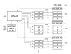
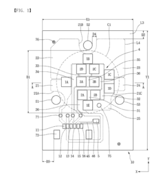
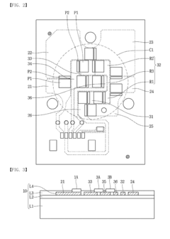
[0056]FIG. 1 is a plan view of a light emitting module according to a first embodiment. FIG. 2 is a plan view of a circuit board of the light emitting module of FIG. 1. FIG. 3 is a cross-sectional view of the light emitting module of FIG. 1, taken along line A-A. FIG. 4 is a circuit configuration view of the light emitting module of FIG. 1. FIG. 5 is a view illustrating an example of arranging light emitting devices in the light emitting module of FIG. 1. FIG. 6 is a view illustrating comparison widths of the light emitting device and a wiring in the light emitting module of FIG. 1. FIG. 7 is a view for explaining a form of arranging the light emitting devices in the light emitting module of FIG. 1.

[0057]Referring to FIGS. 1 to 7, the light emitting module may include a circuit board 10 and a light source unit 4 disposed on the circuit board 10 and emitt...

second embodiment

[0120]FIG. 8 is a side cross-sectional view of a light emitting module according to a FIG. 9 is a cross-sectional view of the light emitting module of FIG. 8, taken along line B-B. FIG. 10 is a cross-sectional view of the light emitting module of FIG. 9, taken along line C-C.

[0121]Referring to FIG. 8 to FIG. 10, the light emitting module 100 may include the light source unit 4 having the plurality of first to third light emitting devices 1A-1E, 2A-2D, 3A, and 3B according to the embodiment on the circuit board 10, and a reflective member 61 disposed in the circumference of the light source unit 4.

[0122]The light emitting module 100 may include the light source unit 4 having the plurality of first to third light emitting devices 1A-1E, 2A-2D, 3A, and 3B on the circuit board 10 according to the embodiment. This configuration will be provided with reference to the description of the first embodiment.

[0123]The reflective member 61 may be attached onto the circuit board 10. The reflecti...

third embodiment

[0142]FIG. 12 is a view illustrating a light emitting module as another example of the light emitting module of FIG. 9. FIG. 13 is a cross-sectional view of the light emitting module of FIG. 12, taken along line D-D.

[0143]Referring to FIG. 12 and FIG. 13, the light emitting module may include the light source unit 4 having the plurality of first to third light emitting devices 1A-1E, 2A-2D,3A, and 3B disposed on the circuit board 10, the reflective member 61 disposed in the circumference of the light source unit 4, and support protrusions 65 disposed within the reflective member 61.

[0144]The reflective member 61 may be coupled to the plurality of openings 51, 52 and 53 disposed in the circuit board 10. The reflective member 61 may contain a plastic material or a resin material such as silicon or epoxy. The reflective member 61 has a ring shape and may be disposed in the circumference of the light source unit 4. The reflective member 61 may have a circular shape or a polygonal shape...


PUM


Abstract

A lighting apparatus according to an embodiment comprises: a circuit board; and a plurality of light emitting modules having first to third light source units for emitting different colors on the circuit board; a control unit for providing a current control signal for controlling a current of each of the first to third light source units; a driver for controlling currents of the first to third light source units with a current control signal of the control unit, and a memory unit for storing luminous flux deviation data of the first to third light source units of each of the plurality of light emitting modules, wherein the first light source unit includes a plurality of first light emitting devices for emitting red light, and the second light source unit includes a plurality of second light emitting devices for emitting green light, and the third light source unit includes a plurality of third light emitting devices for emitting blue light, and the control unit controls currents of the first, second, and third light source units of the plurality of light emitting modules, respectively, according to an intensity value of an input current corresponding to the luminous flux deviation data.

Description

TECHNICAL FIELD[0001]Embodiments relate to a light emitting module and a lighting apparatus having the same.BACKGROUND ART[0002]A light emitting device such as a light emitting diode, a kind of semiconductor device that converts electrical energy into light, has received considerable attention as the next generation light source that replaces existing fluorescent and incandescent lamps.[0003]A light emitting diode may generate light using a semiconductor device and thus, may consume relatively low power as compared to incandescent lamps generating light by heating tungsten or fluorescent lamps generating light by allowing ultraviolet light generated through high-pressure discharge to collide with phosphors.[0004]In addition, since a light emitting diode generates light by using a potential gap of a semiconductor device, the light emitting diode has a longer lifetime, faster response characteristics, and eco-friendliness as compared with conventional light sources.[0005]Accordingly, ...

Claims


Application Information

Patent Timeline
IPC IPC(8): H05B33/08F21K9/68F21V3/00F21V19/00F21V29/76H05K1/18H05B44/00
CPCH05B33/0869H05B33/0851F21K9/68H05B33/0827F21V3/00F21V19/0015F21V29/76H05K1/181F21Y2115/10F21Y2113/13H05K2201/10106H05K2201/10151F21V7/04F21V29/74F21V29/89H05K1/0203H01L2224/48091H01L2224/73265H01L2224/14F21Y2105/10H05B45/24H05B45/22Y02P70/50H05B47/105H05B45/18H05B45/12H05B47/11Y02B20/40H01L2924/00014F21S2/005F21S10/023F21V7/043F21V23/0457F21V23/0464H01L33/507H05B45/46
Inventor AHN, YOUNG JOOKIM, DO YUBSON, EON HOSHIN, MI NA
Owner SUZHOU LEKIN SEMICON CO LTD