Batch and continuous methods for evaluating the physical and thermal properties of films

Active Publication Date: 2018-03-08
UT BATTELLE LLC +1
View PDF6 Cites 5 Cited by
  • Summary
  • Abstract
  • Description
  • Claims
  • Application Information

AI Technical Summary

Benefits of technology

[0006]For these reasons, it is apparent that there exists a need for fast, reliable, non-destructive, and cost-effective, online evaluation of thin films, membranes and electrodes, especially for large-scale, continuous manufacturin

Problems solved by technology

However, the performance, life, and ultimately the cost of films depend heavily on how they are manufactured.
In addition, physical defects within the films and/or at their surfaces, for example scuffs, scores, slits, bubbles, pinholes, bubbles, agglomerates, occlusions and/or other bulk and/or surface inhomogeneities may be especially detrimental t

Method used


Image

  • Batch and continuous methods for evaluating the physical and thermal properties of films
  • Batch and continuous methods for evaluating the physical and thermal properties of films
  • Batch and continuous methods for evaluating the physical and thermal properties of films

Examples


example 1

[0132]Referring to FIG. 14, a battery electrode 700 was positioned on glass rods 710 and 720 to minimize conductive heat losses to the environment. The electrode 700 was a bilayer electrode constructed from a top porous film 702 positioned in direct physical contact with a bottom metallic film 704. In this example, the top film 702 was a 75 micron thick Li ion battery cathode constructed of NMC532 particles, Denka Black particles and PVDF polymer binder. The bottom film 504 was a 15 micron thick Aluminum film. A tungsten halogen line radiation source 200 was used to provide the energy input to the battery electrode 700 by focusing the light through a lens 740. In this example, the halogen radiation source 200 provided a power input of about 200 mW / cm2. The radiation source 200 applied radiation to the battery electrode 700 in a static set-up where neither the light, the thermal response detector 400, nor the electrode was moved during the illuminating. A starting temperature of the ...

example 2

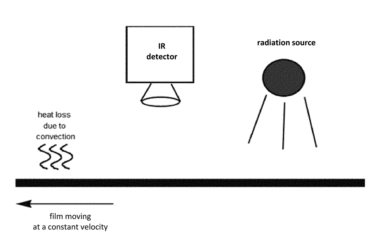
[0136]This example summarizes the results obtained from one embodiment of the present disclosure, where the films were not held statically, but instead were moved in a linear direction relative to a fixed radiation source and a fixed detector. This experiment investigated another embodiment of the present disclosure, one that simulated continuous evaluation of a moving film (relative to the energy source and the thermal response detector), as might occur in a large-scale, continuous manufacturing plant. Specifically, the same basic experimental setup as described above for FIG. 14 was utilized, except that the film was moved from right to left at a speed of about 0.1 inches / second underneath a fixed LED line radiation source (the radiation source) and a fixed IR camera (the detector). The radiation source and the detector were positioned on the same side of the film. The camera's field of view was about 6 inches by 6 inches (in the X and Y directions) and the field of view included ...

example 3

[0139]This example illustrates a process for measuring the porosity of Li ion battery electrodes, utilizing one or more heated rollers for providing heat transfer to the electrodes to cause a measurable temperature change within the electrodes. In this example, the micro-structure of the electrodes includes two main layers as shown in FIG. 19: a metal (aluminum or copper) foil base layer on which is positioned a layer of functional particles joined together by a polymer binder. The porosity of the functional particle layer may be substantial, typically in the 40-60% range. Monitoring and precise control of this porosity is crucial for proper operation of the final battery that utilizes the electrodes. The functional particle layer is formed in a die coater process, with the resultant coating dried in an oven. After drying the electrode bilayer film may be passed through an evaluation system that includes a heated roller and a detector to perform an in-line evaluation of the function...


PUM


Abstract

Thermal methods and systems are described for the batch and/or continuous monitoring of films and/or membranes and/or electrodes produced in large-scale manufacturing lines. Some of the methods described include providing an energy input into a film, measuring a thermal response of the film, and correlating these to one or more physical properties and/or characteristics of the film.

Description

CROSS-REFERENCE TO RELATED APPLICATIONS[0001]This application claims priority to PCT / IB2016 / 051314 filed Mar. 8, 2016, having the same title, and the same inventors, which claims the benefit of U.S. Provisional Application No. 62 / 130,346 filed Mar. 9, 2015, the contents of which are incorporated herein by reference in their entirety.CONTRACTUAL ORIGIN[0002]The United States Government has rights in this invention under Contract No. DE-AC36-08GO28308 between the United States Department of Energy and the Alliance for Sustainable Energy, LLC, the Manager and Operator of the National Renewable Energy Laboratory. This invention was made with government support under Contract No. DE-AC05-00OR22725 awarded by the U.S. Department of Energy. The government has certain rights in the invention.BACKGROUND[0003]Various forms of membranes and thin films find numerous industrial and commercial uses. For example, these materials are frequently used in separation processes, including water treatmen...

Claims


Application Information

Patent Timeline
IPC IPC(8): G01B21/08G01N25/18G01N15/08G01N9/00
CPCG01B21/085G01N25/18G01N15/088G01N9/00G01N2015/086G01N25/005
Inventor SOPORI, BHUSHAN LALULSH, MICHAEL JOSEPHRUPNOWSKI, PRZEMYSLAWBENDER, GUIDOPENEV, MICHAEL MIHAYLOVLI, JIANLINWOOD, III, DAVID L.DANIEL, CLAUS
Owner UT BATTELLE LLC
Why Eureka
Try Eureka