High-frequency transmission line and optical circuit

a high-frequency transmission line and optical circuit technology, applied in waveguide devices, semiconductor lasers, instruments, etc., can solve the problems of general difficulty in achieving impedance matching in a wider bandwidth, and achieve the effect of improving the high-frequency characteristi

Active Publication Date: 2018-03-08
NIPPON TELEGRAPH & TELEPHONE CORP
View PDF3 Cites 5 Cited by
  • Summary
  • Abstract
  • Description
  • Claims
  • Application Information

AI Technical Summary

Benefits of technology

[0072]According to the present invention, the high-frequency characteristic is improved.

Problems solved by technology

Thus, it is generally difficult to achieve the impedance matching in a wider bandwidth including a high-frequency region exceeding 10 GHz for example, by only using resistance material only having a real part value of impedance.

Method used


Image

  • High-frequency transmission line and optical circuit
  • High-frequency transmission line and optical circuit
  • High-frequency transmission line and optical circuit

Examples


modification example 1

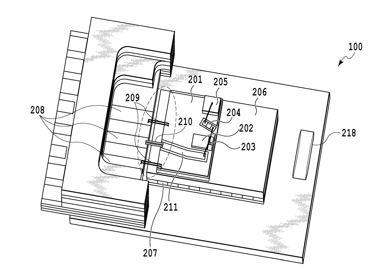
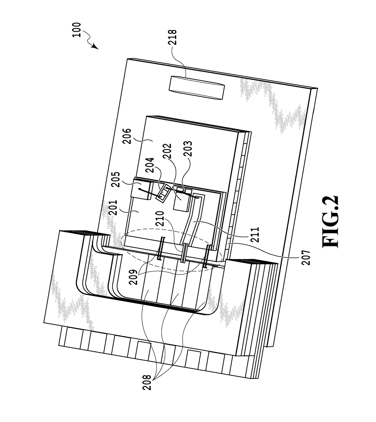
[0141]In the above description, a case was described in which the EAM 804 of the EML was connected between the conductor line 801 and the ground line 802. However, another case also may be considered in which the EAM 804 has the signal electrode and the ground electrode formed on different faces. FIG. 21 illustrates such a case in which the high-frequency transmission line 1A is configured so that the signal electrode and the ground electrode of the EAM are both flip chip-bonded by the first conductor line 11 for example.

modification example 2

[0142]The above-described bent shapes (tapered shapes) 13a to 13d may be the ones that allow the characteristic impedance to be higher than 50Ω for example and also may be substituted with various other shapes. For example, the bent shapes may be changed in a stepwise, curved, or continuous manner.

modification example 3

[0143]In the ones shown in FIG. 12 and FIG. 21, the tapered shape may be formed only in the first conductor line 11 and may not be formed in the ground line 12.


PUM

PropertyMeasurementUnit
impedanceaaaaaaaaaa
output impedanceaaaaaaaaaa
termination resistanceaaaaaaaaaa

Abstract

A high-frequency transmission line is provided that improves a high-frequency characteristic. The high-frequency transmission line includes a first conductor line, a termination resistance connected to the first conductor line, a second conductor line connected to the termination resistance, and a ground line that is provided to be opposed to the first conductor line, the termination resistance, and the second conductor line to have a predetermined distance thereto and that is connected to the second conductor line. The first conductor line and the ground line are formed to have a line width decreasing toward the termination resistance, respectively.

Description

TECHNICAL FIELD[0001]The present invention relates to a termination technique for an optical device operating with a high frequency such as an optical transmitter for optical communication. In particular, the invention relates to a 50 ohm termination technique for an Electroabsorption Modulator (EAM) integrated with a Distributed Feedback (DFB) Laser (EML).BACKGROUND ART[0002]In recent years, a required communication capacity has been rapidly increasing due to the increase of the use of the Internet, IP telephone, or the downloading of video for example. A demand has been increasing for optical fibers and optical transmitters provided in optical communication machines. An optical transmitter or a component constituting the optical transmitter is called as a Pluggable and has been subjected to rapid modularization based on the specification for easy mounting or exchange.[0003]XFP (10 Gigabit Small Form Factor Pluggable) is one of the industrial standards for a removable module based ...

Claims


Application Information

Patent Timeline
Patent Type & Authority Applications(United States)
IPC IPC(8): G02F1/015H04B10/50H01S5/042H01S5/0625H01S5/026H04B10/516H01S5/12
CPCG02F1/015H04B10/503H01S5/0425H01S5/06258H01S5/026H04B10/516G02F2001/0157H04B3/00H01P5/028H01S5/0265H01S5/1039H01S5/12H01S5/04257H01S2301/176H01S5/4031H01S5/4012H01S5/0427H01S5/0237H01S5/042G02F1/0157
Inventor KANAZAWA, SHIGERUUEDA, YUTAOZAKI, JOSUKE
Owner NIPPON TELEGRAPH & TELEPHONE CORP
Why Eureka
Try Eureka