Dust core

a technology of dust core and dust core, which is applied in the direction of core/yokes, inductance/transformer/magnet manufacturing, transportation and packaging, etc., can solve the problems of low corrosion resistance of glass coating, poor corrosion resistance of dust core material, and winding insulation breaking down

Active Publication Date: 2018-03-08
TDK CORPARATION
View PDF2 Cites 4 Cited by
  • Summary
  • Abstract
  • Description
  • Claims
  • Application Information

AI Technical Summary

Benefits of technology

[0045]The dust core according to the present embodiments have the metal magnetic powder and the resin, and is fixed to a predetermined form by binding a plurality of the metal magnetic particles constituting the metal magnetic powder via the resin.
[0046]Such dust core is preferably used as the core of the coil type electronic components. For instance, the dust core may be a coil type electronic component in which an air-core coil where a wire is wound around is buried in said dust core of a predetermined shape, or a coil type electronic component in which a wire is wound around on the surface of the dust core for a predetermined winding number. A formation of the core where the wire wound around may exemplify FT type, ET type, EI type, UU type, EE type, EER type, UI type, drum type, toroidal type, pot type, cup type, etc.
[0047]The metal magnetic powder configuring the dust core according to the present embodiment is an aggregate of a plural number of the metal magnetic particles. According to the present embodiment, the particle size distribution of the metal magnetic powder is within a range of more than 0 μm and 200 μm or less. In addition, according to the present embodiment, the particle diameter of the metal magnetic particles is measured as mentioned below.
[0048]A f...

Problems solved by technology

However, a material composing the dust core is a metal mainly composed of Fe, therefore, there was a problem that material configuring the dust core was inferior in a corrosion-resistance, especially in a rustproof property, under a moist condition.
However, there is a problem that the corrosion-resistance of the glass coat...

Method used


Image

  • Dust core
  • Dust core
  • Dust core

Examples


example 1

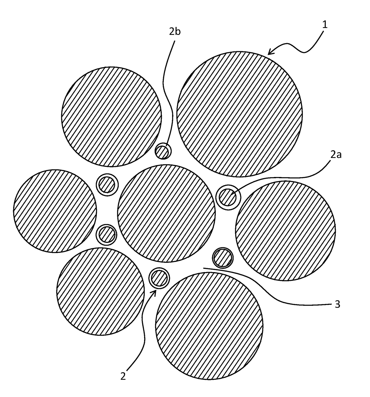
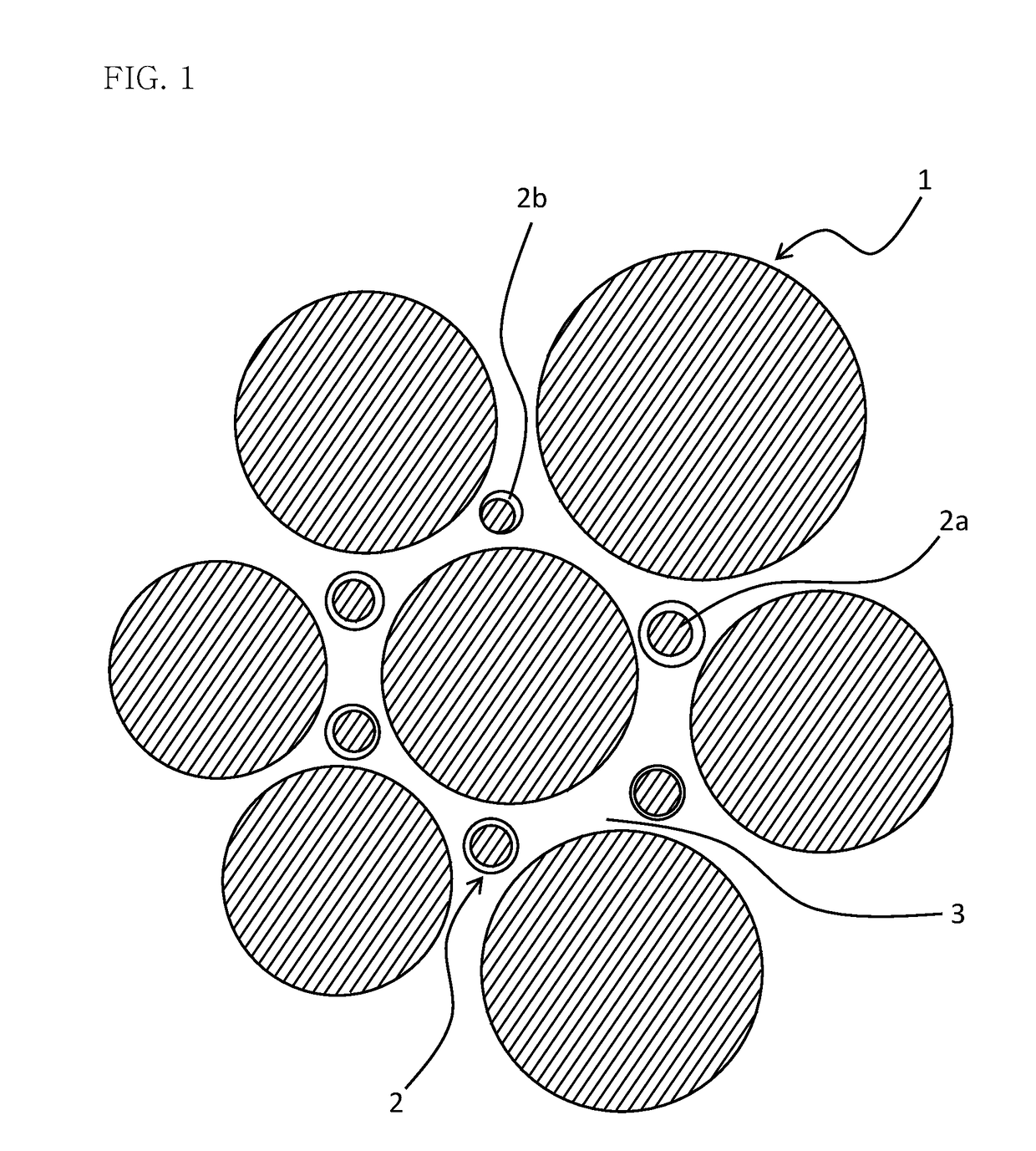
[0093]First, eight kinds of powders, powders A to F, composed by the metal magnetic particles of a Fe—Si based alloy, having the same particle size distribution, were prepared as the metal magnetic powder. The coating part was not formed on the metal magnetic particles of powder A, and the coating part was formed on the metal magnetic particles of powder B-1 to powder F by the methods shown below.

[0094]Powder B-1 was coated by a wet coating method with the inorganic compound including MgO and Al2O3. First, the ionic crystals of Mg source and the same of Al source were dissolved in acetone, the powder B-1 was added to the acetone and mixed thereof, and slurried thereof. The obtained slurry was evaporated and dried, then the dried powder was heat treated at 600° C. for 10 h., and the coating part configured by the inorganic compound including MgO was formed on the metal magnetic particles.

[0095]Powder B-2 was coated by a wet coating method with the inorganic compound including BaO and...

example 2

[0110]The dust core was manufactured similarly to the same of Ex. 1, except forming the coating part on the metal magnetic particles of particle B-1 using the inorganic compound, in which the content ratios of MgO and Al2O3 were varied, and then varying the particle size distributions of powder A and powder B-1 by screening powder A and powder B-1. The same evaluation as in Ex. 1 was performed. Results are shown in Table 2.

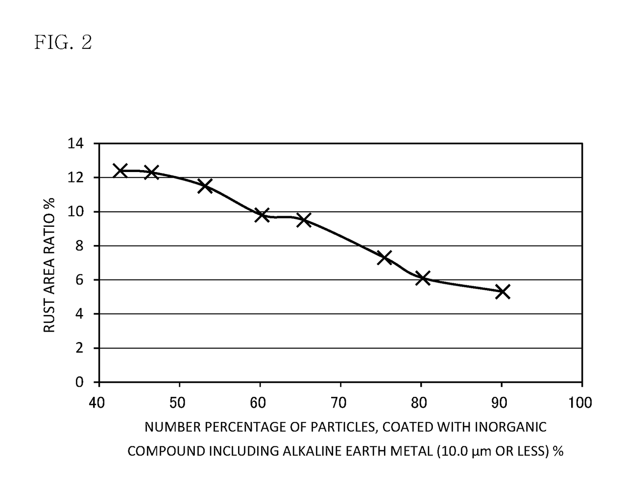
TABLE 2Number percentage of Coated particles [%]Coated PartParticle size distributionAlkalineAlkaline earthAlkaline earthAlkaline earthRust areain dust core [μm]earthmetalmetalContentmetal amountratioEx.d10d50d90metalOthers(10.0 μm or less)(5.0 μm or less)materials[mass %][%]Comp. Ex. 2-13.519.740.515.6042.451.2MgO + Al2O38.523.1Comp. Ex. 2-23.219.639.114.9042.551.3MgO + Al2O39.522.1Ex. 2-14.119.539.915.1042.451.2MgO + Al2O310.312.4Ex. 2-23.119.439.315.5042.451.2MgO + Al2O311.211.5Ex. 2-33.119.638.915.7042.551.3MgO + Al2O319.111.2Ex. 2-42.619.238.216.1042.551.3MgO...

example 3

[0112]As the metal magnetic powder, powder G having approx. 5 μm of d99 according to the metal magnetic particles and powder H having approx. 10 μm of d99 according to the metal magnetic particles, respectively made of Fe were prepared. As the metal magnetic powder, powders G and H, made of Fe, and the metal magnetic particles thereof showing d99 of approx. 5 μm and approx. 10 μm respectively were prepared. The inorganic compound including MgO was coated on Powders G and H by the coating treatment of the wet method. First, ionic crystals of Mg source was dissolved in acetone, each powder was added to the acetone, and mixed thereof to make a slurry. The obtained slurry was evaporated and dried, the dried powder was heat treated at 600° C. for 10 hours, and then the coating part composed of the inorganic compound including MgO was formed on Powder G and Powder H. The coated powders were suitably mixed with Powder C. From the processes, the metal magnetic powder in which the number per...


PUM

PropertyMeasurementUnit
Lengthaaaaaaaaaa
Lengthaaaaaaaaaa
Fractionaaaaaaaaaa

Abstract

A dust core including a metal magnetic powder and a resin, in which the metal magnetic powder shows a particle diameter of more than 0 μm and 200 μm or less, a number percentage of 5.0% or more of metal magnetic particles among the metal magnetic particles composing the metal magnetic powder are at least partially surface-coated with an inorganic compound including an alkaline earth metal, in a coating part coating the metal magnetic particles, an amount of the alkaline earth metal is 10.0 mass % or more, when a total amount of a metal element included in the coating part is 100 mass %, is provide. The dust core is superior in a corrosion-resistance.

Description

BACKGROUND OF THE INVENTION1. Field of the Invention[0001]The present invention relates to a dust core.2. Description of the Related Art[0002]As an electronic component used for the power circuit of various electronic devices for a consumer use and also for an automobile use, coil type electronic components such as a transformer, a choke coil, an inductor, etc. are known. In addition, such as a motor is known as a machine component utilizing the coil.[0003]Such coil type electronic components and the motor have a configuration in which a coil, a winding wire, of an electrical conductor is disposed inside or circumference of the magnetic body exhibiting a predetermined magnetic characteristic. Various materials can be used for the magnetic body corresponding to a desired characteristic. Conventionally, in the coil type electronic components, the ferrite material having a high permeability and a low power loss are used for the magnetic body.[0004]Recently, in order to correspond to th...

Claims


Application Information

Patent Timeline
IPC IPC(8): H01F1/24H01F41/02B29B7/90B29C43/00B22F1/10B22F1/16
CPCH01F1/24H01F41/0246B29B7/90B29C43/003B29K2105/16B29K2505/00B29K2995/0008H01F27/255B22F1/16B22F1/10B22F2998/10B22F9/026B22F3/1039C22C33/02B22F2999/00C22C2202/02B22F1/05H01F3/08C22C38/00C22C38/02C22C38/06C22C38/08C22C38/10C22C45/02B22F9/082
Inventor NAKAZAWA, RYOMAFUTAMATA, YOUSUKETAKAHASHI, TAKESHI
Owner TDK CORPARATION
Why Eureka
Try Eureka