High-frequency transformer design for dc/dc resonant converters

a high-frequency transformer and resonant converter technology, applied in the direction of process and machine control, instruments, printed circuit non-printed electric components association, etc., can solve the problems of large total size of the transformer assembly, large ac loss and large dc resistance loss, and difficult to achieve high efficiency. , to achieve the effect of reducing leakage inductance and low voltage spik

Active Publication Date: 2018-03-08
MURATA MFG CO LTD
View PDF15 Cites 5 Cited by
  • Summary
  • Abstract
  • Description
  • Claims
  • Application Information

AI Technical Summary

Benefits of technology

[0016]4) Low voltage spike on drain to source of MOSFETs Q3 and Q4 by reducin...

Problems solved by technology

The skin depth effect and the proximity effect can generate large AC loss and large DC resistance loss.
Although this known transformer structure can achieve high efficiency, the total size of the transformer assembly is considerably large.
Alth...

Method used


Image

  • High-frequency transformer design for dc/dc resonant converters
  • High-frequency transformer design for dc/dc resonant converters
  • High-frequency transformer design for dc/dc resonant converters

Examples


Embodiment Construction

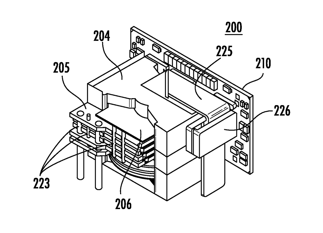
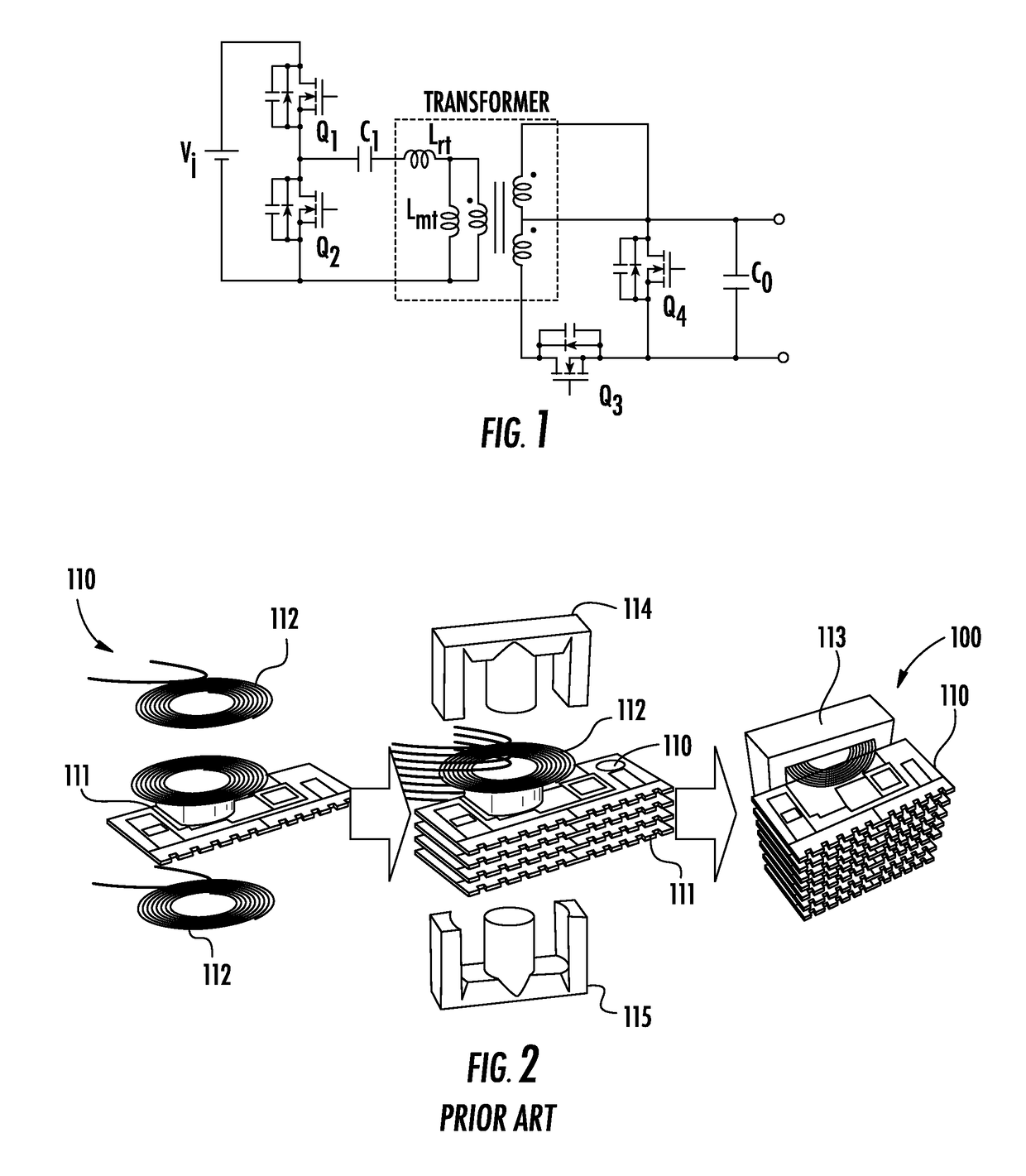
[0032]Preferred embodiments of the present invention relate to high-frequency transformer design for DC / DC resonant converters such as parallel LC, LLC, LCLC, etc. FIG. 5 is a circuit diagram of the secondary-side of a DC / DC resonant converter. FIG. 12 shows the transformer assembly 200 that implements that circuit shown in FIG. 5. The transformer assembly 200 includes transformer 204 and output-rectifier PCB 210. The output rectifier PCB 210 can be any suitable substrate. FIGS. 6-9 shows the output-rectifier PCB 210. FIGS. 10 and 11 show the transformer 204 with primary windings 201, secondary windings 202, and magnetic core 203. As shown in FIG. 10, the primary windings 201 can be located on multiple PCBs 205 and the secondary windings 202 can be made of stamped copper 206. The primary windings 201 do not have to be located on PCBs 205. The primary windings 201 can, for example, be made of Litz wire. The secondary windings do not have to be made of stamped copper. The secondary wi...


PUM


Abstract

A transformer assembly includes a transformer with primary windings located on multiple layers and with secondary windings interleaved with the multiple layers and includes a substrate connected to the transformer and with a first transistor with first, second, and third terminals, in which the first terminal is connected to the secondary windings, the second terminal is connected to an output terminal of the transformer assembly, and the third terminal is a control terminal; first conductive layers; second conductive layers interleaved with the first conductive layers; a first via that is solid filled and that connects the first conductive layers and the first terminal; and a second via that is solid filled and that connects the second conductive layers and the second terminal.

Description

BACKGROUND OF THE INVENTION1. Field of the Invention[0001]The present invention relates to DC / DC resonant converters. More specifically, the present invention relates to high-frequency transformer design for DC / DC resonant converters.2. Description of the Related Art[0002]A half-bridge LLC converter is shown in FIG. 1. The half-bridge LLC converter shown in FIG. 1 can be used either with the known transformers discussed in this section or with the novel transformers according to the preferred embodiments of the present invention discussed in the Detailed Description of Preferred Embodiments section below.[0003]FIG. 1 shows a typical application of a half-bridge DC-DC converter using an LLC series resonant circuit. In FIG. 1, “primary side” refers to the portion of the circuit on the left-hand side of the transformer connected to the primary windings, and “secondary side” refers to the portion of the circuit on the right-hand side of the transformer connected to the secondary winding...

Claims


Application Information

Patent Timeline
IPC IPC(8): H01F27/34H02M3/335H05K7/20H01F27/40H01F27/29H05K1/18H05K1/11
CPCH01F27/346H02M3/33592H05K7/209H01F27/40H01F27/29H05K1/181H05K1/111H01F2027/065H05K2201/1003H01F27/2804H01F2027/2819H02M3/335Y02B70/10H02M1/0058
Inventor AFSHARIAN, JAHANGIRGONG, BINGATHAB, HUSSAIN S.
Owner MURATA MFG CO LTD
Why Eureka
Try Eureka