Structures, system and method for converting electromagnetic radiation to electrical energy using metamaterials, rectennas and compensation structures

a technology of electromagnetic radiation and metamaterials, applied in the structure of radiating elements, resonant antennas, antenna earthings, etc., can solve the problems of inefficient conversion process used in these plants, high cost of conventional turbine-based solutions for generating electricity from heat, and inefficient production of heat, so as to achieve better operation points and more efficient power harvesting

Inactive Publication Date: 2018-03-15
REDWAVE ENERGY
View PDF13 Cites 25 Cited by
  • Summary
  • Abstract
  • Description
  • Claims
  • Application Information

AI Technical Summary

Benefits of technology

[0021]An advantage of compensation circuits as disclosed herein is the tradeoff of antenna current for voltage. This is particularly useful because supplying a higher voltage to the diode places it in a better operating point along its current-voltage characteristic. Moreover, this tradeoff matches the low impedance of the antenna (about 100 ohms) to the higher impedance diode.
[0022]Another advantage of compensation circuits as disclosed herein is in smoothing out the shape of the voltage and current in the circuit. Compensation circuits as disclosed herei

Problems solved by technology

Unfortunately, the conversion processes used in these plants are inefficient, and often produce more heat as waste than is converted into electricity.
Conventional turbine-based solutions for generating electricity from heat are expensive.
Despite the maturity of turbine-based systems, high cost and greater demand for electricity make new technologies that convert heat to electricity more efficiently and at lower cost increasingly attractive.
TPV technology faces a number of hurdles in converting heat to electricity.
As a result, these lower energy photons are absorbed

Method used


Image

  • Structures, system and method for converting electromagnetic radiation to electrical energy using metamaterials, rectennas and compensation structures
  • Structures, system and method for converting electromagnetic radiation to electrical energy using metamaterials, rectennas and compensation structures
  • Structures, system and method for converting electromagnetic radiation to electrical energy using metamaterials, rectennas and compensation structures

Examples


Embodiment Construction

[0072]The following description is presented to enable one of ordinary skill in the art to make and use the invention and is provided in the context of a patent application and its requirements. Various modifications to the described embodiments will be readily apparent to those skilled in the art and the generic principles herein may be applied to other embodiments. Thus, the present invention is not intended to be limited to the embodiments shown but is to be accorded the widest scope consistent with the principles and features described herein.

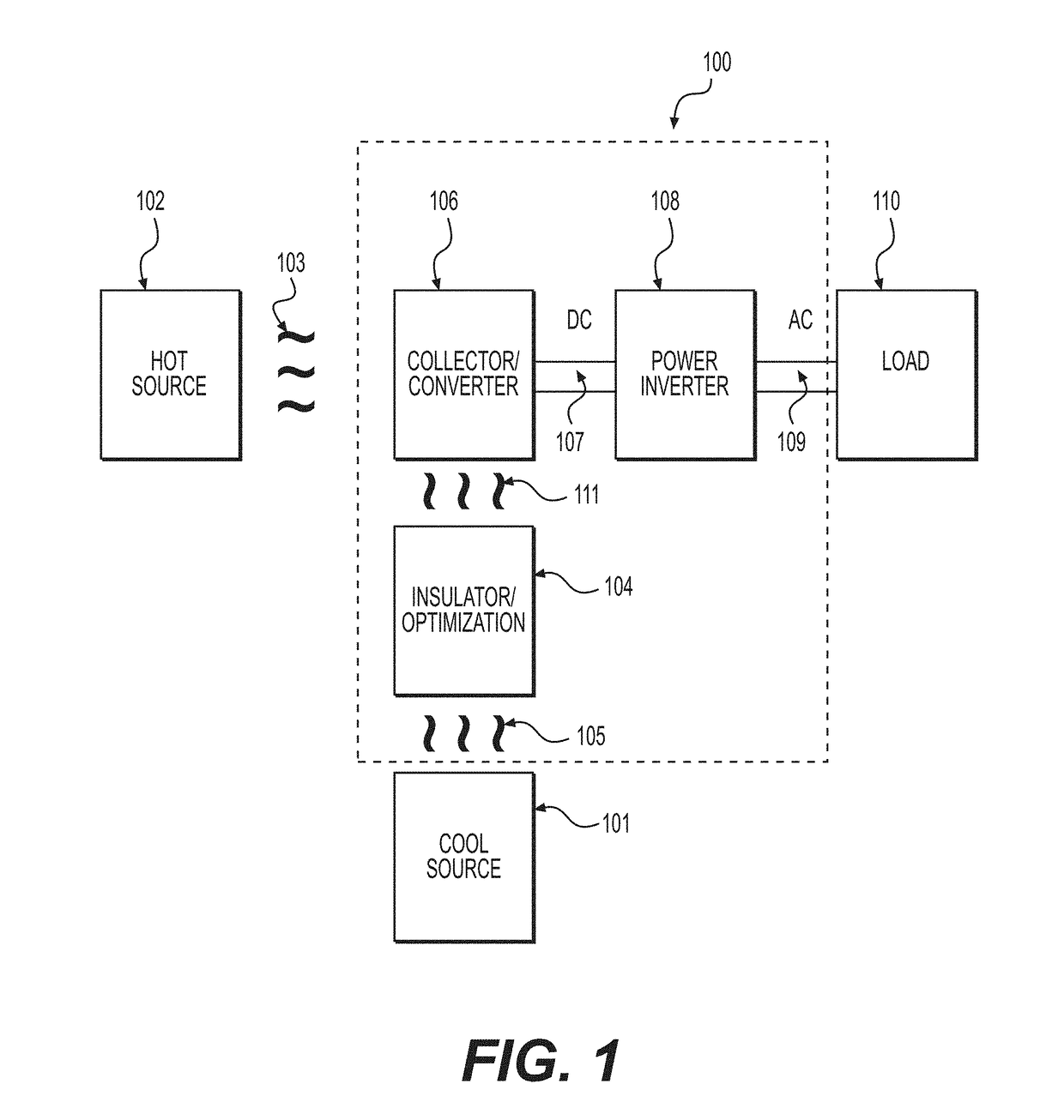
[0073]FIG. 1 is a schematic diagram of a system 100 for harvesting energy from a heat source 102 and supplying the generated electricity to a load 110. A collector / converter device 106 collects heat 103 provided by heat source 102 and converts that heat to direct current (DC). In embodiments, the DC is converted to alternating current (AC) by coupling collector / inverter 106 to a power inverter 108 over a bus 107. The generated AC can then b...


PUM


Abstract

A metamaterial coupled antenna includes a metamaterial and a rectenna that has an antenna element and a diode coupled by a transmission line. The metamaterial generates a spoof surface plasmon in the presence of heat. The antenna element resonates in the presence of the spoof surface plasmon as terahertz frequencies and generates a voltage that is coupled to the diode via the transmission line. The diode rectifies the voltage to produce electricity. The transmission line is configured to provide a voltage boost to the voltage signal delivered by the antenna element and to compensation for diode capacitance.

Description

[0001]The present application claims the benefit of U.S. Provisional App. No. 62 / 394,679, filed Sep. 14, 2016, which is hereby incorporated by reference herein in its entirety.BACKGROUNDField of the Invention[0002]Embodiments of the present invention relate generally to structures and methods for harvesting energy from electromagnetic radiation. More specifically, embodiments relate to systems for harvesting energy from, for example, the infrared and near infrared (such as heat) and visible spectrums and capturing terahertz energy.Background of the Invention[0003]There is a great need for inexpensive renewable energy in the world. Ironically, there is an abundance of energy available in the form of sunlight and heat. Using such energy to support modern living, however, requires that energy be converted into electrical form. In fact, most electrical energy used today comes from a conversion process involving heat. For example, nuclear, coal, diesel, and natural gas powered electrical...

Claims


Application Information

Patent Timeline
IPC IPC(8): H01L35/32H01Q1/22H01L35/22H01L35/02
CPCH01L35/32H01Q1/22H01L35/22H01L35/02H01Q1/38H01Q9/28H01Q15/0086H01Q5/328H01Q1/248H01Q1/48H10N10/80H10N10/855H10N10/17
Inventor BRADY, PATRICK K.HERNER, SCOTT BRADKOTTER, DALE K.PARK, WOUNJHANGMIDYA, PALLAB
Owner REDWAVE ENERGY
Why Eureka
Try Eureka