Eureka AIR delivers breakthrough ideas for toughest innovation challenges, trusted by R&D personnel around the world.

Rotary feed-through for mounting a rotating substrate tube in a lathe, a CVD lathe and a corresponding method using the CVD lathe

a technology of rotating substrate and rotary feed-through, which is applied in the direction of glass making apparatus, manufacturing tools, etc., can solve the problems of increased attenuation loss, cumbersome and radical process, and serious attenuation of the signal being carried, and achieves simple and cost-effective implementation.

Active Publication Date: 2018-03-22
DRAKA COMTEQ BV
View PDF4 Cites 1 Cited by
  • Summary
  • Abstract
  • Description
  • Claims
  • Application Information

AI Technical Summary

Benefits of technology

The present invention is a simple and cost-effective solution to a problem that doesn't require significant changes to the existing instrumental setup or devices / apparatuses. This makes it easy to implement the solution and provides a viable alternative to the existing solutions.

Problems solved by technology

The use of such a fibre for telecommunication purposes requires the fibre to be substantially free from contamination, since such contamination can cause serious attenuation of the signal being carried if great fibre lengths are used.
Although prior art methods exist for preventing the incorporation of such —OH-groups into the optical glass fibre, for example by carrying out a chlorination step following the deposition step in the case of porous glass structures, as known from U.S. Pat. No. 4,675,038, or by adding fluorine during the chemical vapour deposition reaction, for example, as known from European patent application No. 0 127 227, both prior art methods have this drawback that an additional amount of chlorine or fluorine, respectively, will find its way in the final glass structure, leading to increased attenuation losses caused by Rayleigh scattering.
The downside of such a method is that the complete CVD lathe thus has to be placed in a conditioned atmosphere, such that no contamination is able to enter the substrate tube.
This may be a cumbersome and radical process as this would probably involve a redesign of the factory layout.

Method used


Image

  • Rotary feed-through for mounting a rotating substrate tube in a lathe, a CVD lathe and a corresponding method using the CVD lathe
  • Rotary feed-through for mounting a rotating substrate tube in a lathe, a CVD lathe and a corresponding method using the CVD lathe
  • Rotary feed-through for mounting a rotating substrate tube in a lathe, a CVD lathe and a corresponding method using the CVD lathe

Examples


Embodiment Construction

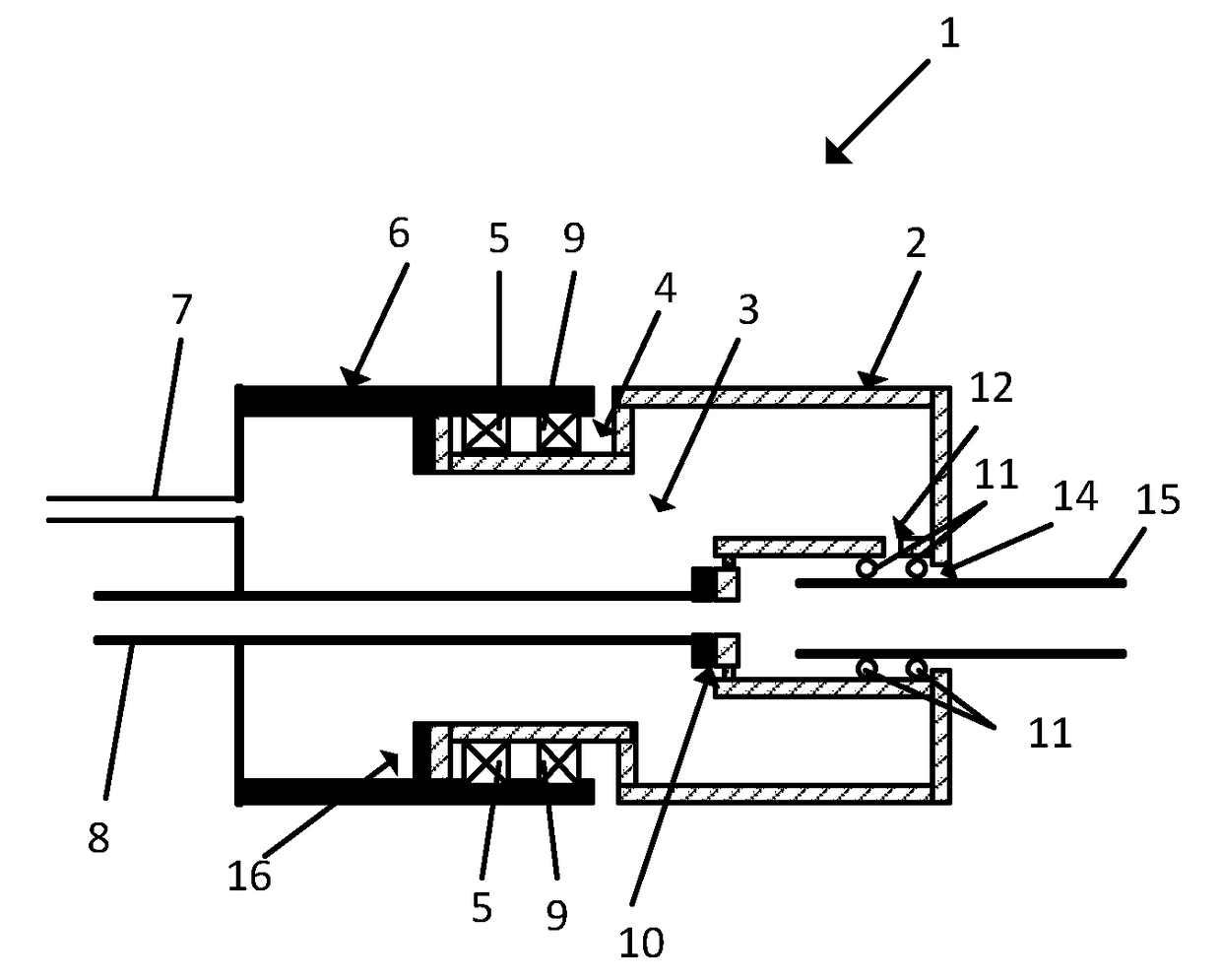
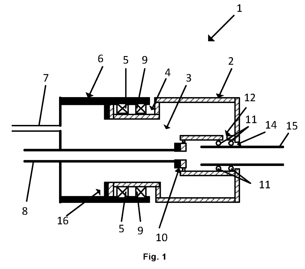
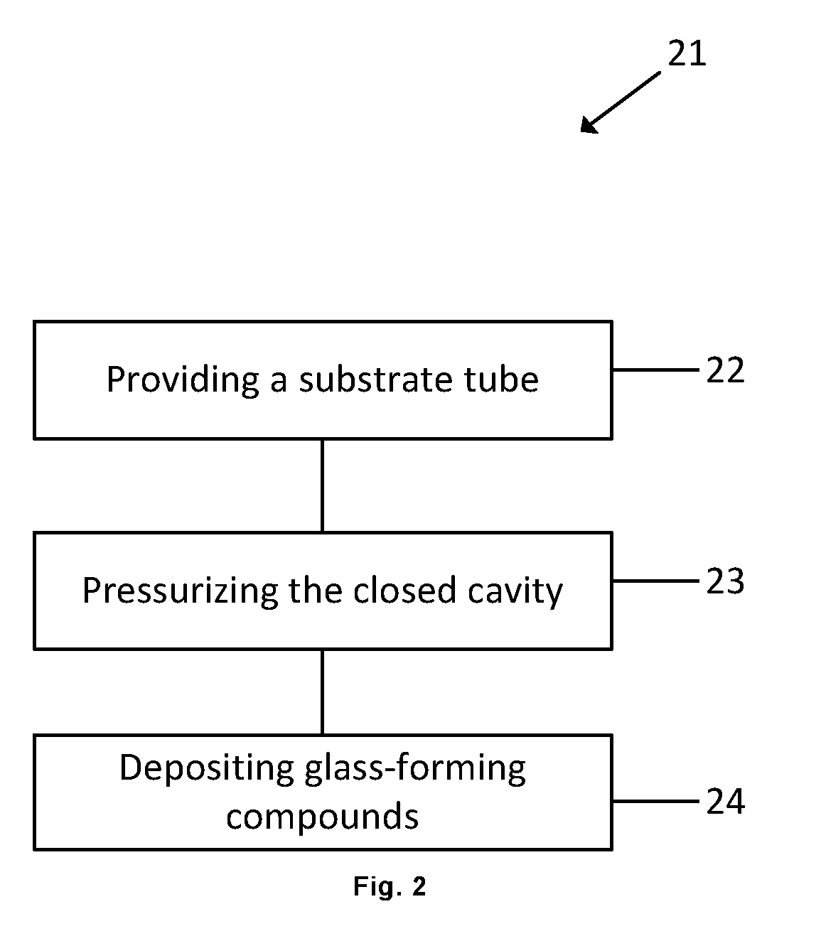
[0054]The present invention relates, in a first aspect, to a rotary feed-through for mounting a rotating substrate tube in a lathe and providing a flow of process gas into the tube, said feed-through comprising:[0055]a process gas supply line for providing a process gas into said substrate tube;[0056]a rotatable holder arranged for receiving and holding said substrate tube for rotating said substrate tube with respect to said process gas supply line;[0057]a rotary union provided between said rotatable holder and said process gas supply line for rotatably connecting said rotatable holder to said process gas supply line;[0058]a stationary housing connected to said process gas supply line and to said rotatable holder, therewith forming a closed cavity surrounding said rotary union, wherein said stationary housing further comprises an auxiliary gas supply line for providing said closed cavity with an auxiliary gas.[0059]a further rotary union provided between said rotatable holder and s...


PUM

PropertyMeasurementUnit
pressureaaaaaaaaaa
pressureaaaaaaaaaa
pressureaaaaaaaaaa

Abstract

A rotary feed-through for mounting a rotating substrate tube in a lathe and providing a flow of process gas into the tube, said feed-through including a process gas supply line for providing a process gas into said substrate tube, a rotatable holder arranged for receiving and holding said substrate tube for rotating said substrate tube with respect to said process gas supply line, a rotary union provided between said rotatable holder and said process gas supply line for rotatably connecting said rotatable holder to said process gas supply line, a stationary housing connected to said process gas supply line and to said rotatable holder, therewith forming a closed cavity surrounding said rotary union, wherein said stationary housing further includes an auxiliary gas supply line for providing said closed cavity with an auxiliary gas.

Description

DESCRIPTION[0001]The present invention relates to a rotary feed-through for mounting a rotating substrate tube in a lathe and providing a flow of process gas into the substrate tube. The present invention further relates to a method for manufacturing a preform for optical fibres using Chemical Vapour Deposition, CVD, and a lathe comprising the new rotary feed-through.[0002]The deposition of glass layers on the interior of a substrate tube, wherein one or more reactive gases and an oxygen-containing gas are supplied to said substrate tube, is known per se, for example from U.S. Pat. No. 6,260,510 in the name of the present applicant. According to the method that is known therefrom, layers of silicon dioxide, which may or may not be doped (e.g. germanium-doped silicon dioxide), are coated onto the interior surface of a substrate tube consisting of quartz glass, for example. Such a deposition reaction may be carried out by positioning the substrate tube along the cylindrical axis of th...

Claims


Application Information

Patent Timeline
Patent Type & Authority Applications(United States)
IPC IPC(8): C03B37/018
CPCC03B37/01884C03B37/01823C03B37/01807C03B37/0183
Inventor MILICEVIC, IGORHENS, RAOULHARLSUIKER, JOHANNES ANTOONKRABSHUIS, GERTJANVAN STRALEN, MATTHEUS JACOBUS NICOLAAS
Owner DRAKA COMTEQ BV
Why Eureka
Eureka Blog
Learn More