
Hybrid photochemical/plasma reactor devices

a photochemical and hybrid technology, applied in the field of chemical reactors, can solve the problems of limiting the commercial potential of conventional plasma reactor technology, the scale and expense of conventional atmospheric pressure plasma technology, and the high cost and weight of typical plasma-chemical reactors, and the scale and expense of commercial plasma-chemical reactors

Active Publication Date: 2018-04-12
THE BOARD OF TRUSTEES OF THE UNIV OF ILLINOIS
View PDF8 Cites 4 Cited by
  • Summary
  • Abstract
  • Description
  • Claims
  • Application Information

AI Technical Summary

Benefits of technology

The patent describes a method and device for generating a hybrid reaction flow using plasma generated in microchannels. This involves using UV or VUV emissions to interact with the plasma and break chemical bonds in the feedstock gas, resulting in a reaction product. The use of both plasma and UV or VUV emissions allows for a more efficient and effective reaction. The device includes a microchannel plasma array and a UV or VUV emission lamp with electrodes to ignite plasma and stimulate the UV or VUV emission lamp. A common or plural phased time-varying voltage sources drive both the plasma array and the UV or VUV emission lamp. The technical effect of this patent is improved reaction efficiency and productivity using a hybrid of plasma and UV or VUV emissions.

Problems solved by technology

For more than a century, the conversion of nitrogen and hydrogen gases into ammonia has been known and commercialized, but the conventional process involves heating the “feedstock” gases and is terribly energy-inefficient.
An impediment to the wider adoption of commercial plasma-chemical reactors is the scale and expense of conventional atmospheric pressure plasma technology.
The cost, size, weight, and high voltages characteristic of typical plasma-chemical reactors limit the commercial potential of conventional plasma reactor technology.
Ozone treatment is a particularly attractive application of plasma-chemical technology but the cost, size, and weight of most existing systems restrict their value for many commercial uses.
Furthermore, the conversion of feedstock gases into O3 is often inefficient, thereby raising electrical power consumption and cost.
This low efficiency for the conversion of feedstock gas to ozone is a result of the fact that ozone is produced only within, or in the vicinity of, the streamers produced in air or oxygen by large volume DBD systems.
Maintenance of such systems is also problematic owing to a large number of ceramic parts and fouling of device components by nitric acid.
There are additional drawbacks to existing commercial plasma-chemical devices and systems.
Moisture and organic contaminants in the feedstock gas are another problem with conventional ozone generating systems because the system can be fouled and rendered less efficient, or disabled, as a result of nitric acid build up on the reactor wall or on vacuum fittings.
Similar difficulties are faced when attempting to process other gases such as carbon dioxide or water vapor in atmospheric pressure DBD-produced plasmas.
However, because the corona discharge reactors are not flat and the plasma is not confined to microscopic channels, these reactors are not readily or easily combined and, in particular, are not amenable to being stacked.
Furthermore, the voltages required of corona discharge systems are high (multi-kV) and conversion efficiencies (oxygen or air→ozone) are low.
However, fabrication costs associated with channels of extended length present an obstacle to commercialization of this technology for applications that would benefit from ozone production.
Prior UV / VUV lamps have been produced commercially, but are generally expensive, bulky and require a cylindrical geometry.
Despite this accomplishment, however, the cost of photons in this spectral region remains high and reactors based solely on photochemistry do not appear to be attractive for many commercial processes at present.

Method used


Image

  • Hybrid photochemical/plasma reactor devices
  • Hybrid photochemical/plasma reactor devices
  • Hybrid photochemical/plasma reactor devices

Examples


Embodiment Construction

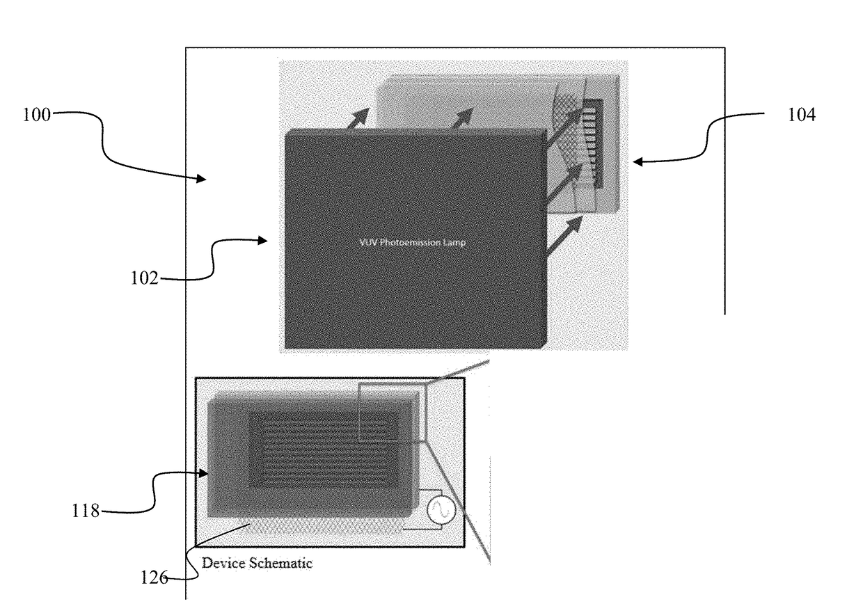
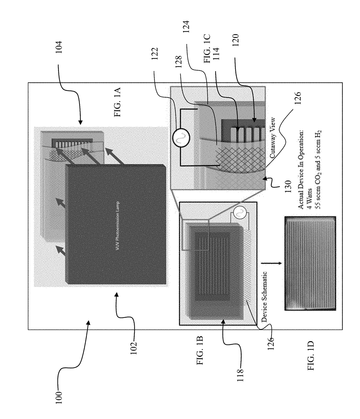
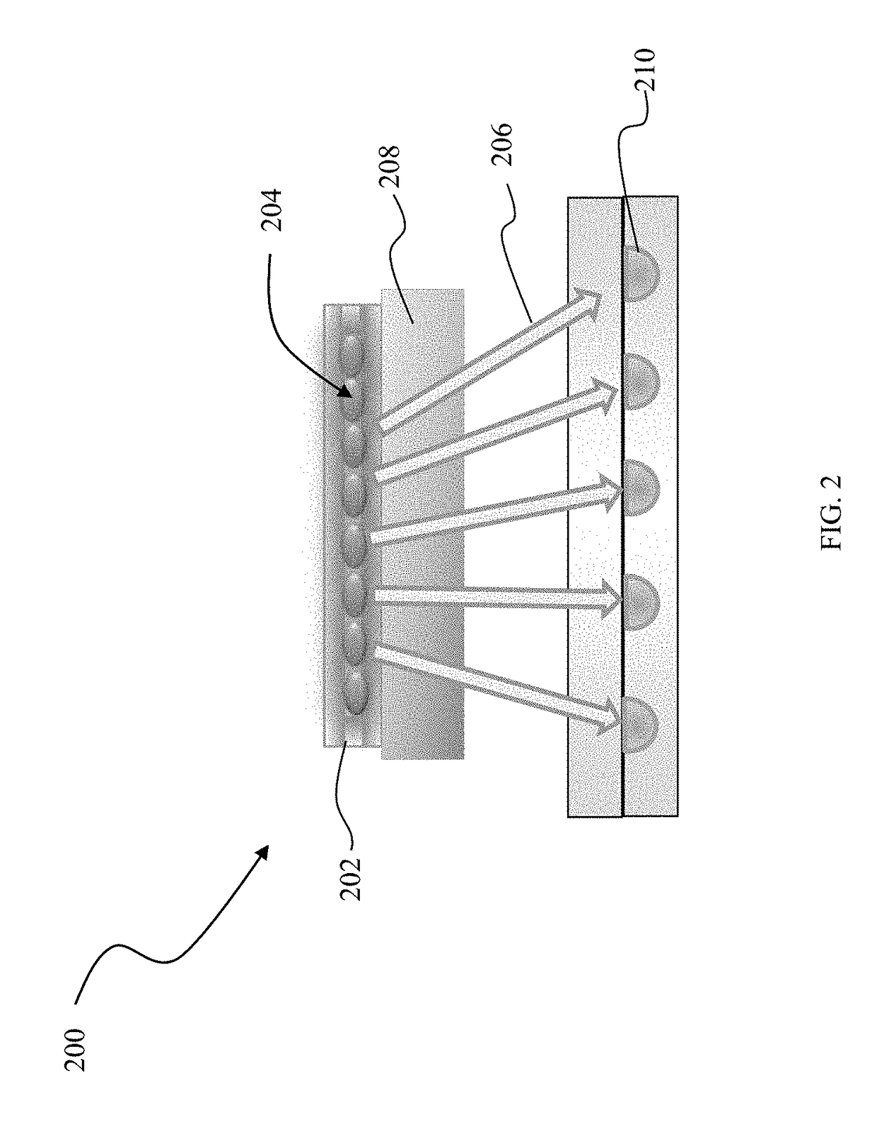
[0032]The present invention introduces a new form of plasmachemical system for converting one or more gases or vapors into another gas (or solid) of commercial value. In the past, such “reactors” have been classified as thermal (i.e., heating the input (feedstock) gases to a critical temperature), plasma (employing a plasma to dissociate or “unravel” the constituent gases) or photochemical (dissociating molecules with light). The vast majority of industrial processes involve the first of these which is generally energy intensive. We have demonstrated a hybrid reactor that combines the latter two processes (plasma and photochemical) by integrating recently-developed, high power vacuum ultraviolet lamps with arrays of microplasmas. The gas conversion processes does not occur at a significant rate if only the microplasmas or the lamps interact separately with the gas(es). That is, a strong synergy is observed when both the plasmas and the lamp(s) (emitting at one or more wavelengths sp...


PUM


Abstract

A method for generating a hybrid reaction flows feedstock gas that is also a plasma medium through microchannels. Plasma is generated with the plasma medium via excitation with a time-varying voltage. UV or VUV emissions are generated at a wavelength selected to break a chemical bond in the feedstock gas. The UV or VUV emissions are directed into the microchannels to interact with the plasma medium and generate a reaction product from the plasma medium. A hybrid reactor device includes a microchannel plasma array having inlets and outlets for respectively flowing gas feedstock into and reaction product out of the microchannel plasma array. A UV or VUV emission lamp has its emissions directed into microchannels of the microchannel plasma array. Electrodes ignite plasma in the microchannels and stimulating the UV or VUV emission lamp to generate UV or VUV emissions. One common or plural phased time-varying voltage sources drive the plasma array and the UV or VUV emission lamp.

Description

PRIORITY CLAIM AND REFERENCE TO RELATED APPLICATION[0001]The application claims priority under 35 U.S.C. § 119 and all applicable statutes and treaties from prior provisional application Ser. No. 62 / 406,018, which was filed Oct. 10, 2016.STATEMENT OF GOVERNMENT INTEREST[0002]This invention was made with Government assistance under U.S. Air Force Office of Scientific Research grant No. FA9550-14-1-0146. The Government has certain rights in this invention.FIELD OF THE INVENTION[0003]The invention is in the field of chemical reactors that convert one or more gases or vapors into another gas, liquid, or solid. Other fields of the invention include microplasma reactor devices. Additional fields of the invention include plasma-chemical reactors, ozone generation, and plasma chemistry.BACKGROUND[0004]An example gas reaction process is widely used for the production of ammonia. For more than a century, the conversion of nitrogen and hydrogen gases into ammonia has been known and commerciali...

Claims


Application Information

Patent Timeline
IPC IPC(8): B01J19/00C01B13/11
CPCB01J19/0093C01B13/115B01J2219/00936B01J2219/0093B01J2219/0095C01B2201/82C01B2201/22B01J2219/00853B01J2219/0086B01J2219/0801B01J2219/0807B01J2219/083B01J2219/0835B01J2219/0841B01J2219/0843B01J2219/0894B01J2219/2402B01J2219/2419B01J2219/00783
Inventor EDEN, JAMES GARYPARK, SUNG-JINSHIN, CHARLESMIRONOV, ANDREY
Owner THE BOARD OF TRUSTEES OF THE UNIV OF ILLINOIS
Learn More