Wind Turbine System or Method of Controlling Wind Turbine System

Inactive Publication Date: 2018-04-12
HITACHI LTD
View PDF8 Cites 6 Cited by
  • Summary
  • Abstract
  • Description
  • Claims
  • Application Information

AI Technical Summary

Benefits of technology

[0014]According to the present invention, it is possible to provide a wind turbine system or a method of controlling the wind turbine system capable of secu

Problems solved by technology

In recent years, global warming due to emission of carbon dioxide, depletion of fossil fuel and the like are regarded as problems from a viewpoint of environmental protection.
However, the output varies directly depending on solar radiation in the solar power generation equipment, therefore, output fluctuation is high and power is not capable of being generated during nighttime.
In the control of rotational speeds, an excessive load is given to the equipment when the rotat

Method used


Image

  • Wind Turbine System or Method of Controlling Wind Turbine System
  • Wind Turbine System or Method of Controlling Wind Turbine System
  • Wind Turbine System or Method of Controlling Wind Turbine System

Examples


Example

Embodiment 1

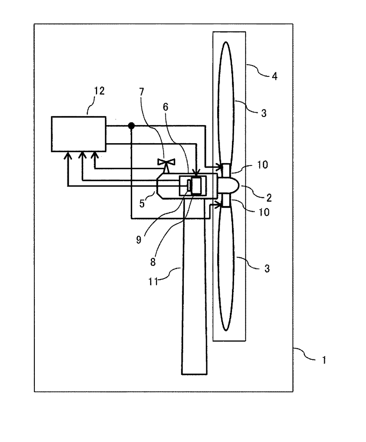
[0031]A wind turbine system according to Embodiment 1 will be explained with reference to FIG. 1 to FIG. 6. FIG. 1 is a schematic configuration diagram of the entire wind turbine system to which the present invention can be applied.

[0032]A wind turbine system 1 of FIG. 1 includes a rotatable rotor 4 including a hub 2 having a rotation shaft (not shown in the drawing) and plural blades 3 attached to the hub 2. The rotor 4 is supported so as to rotate by a nacelle 5 through a not-shown rotation shaft, and a rotation force of the rotor 4 is transmitted to a generator 6 inside the nacelle 5. When the blades 2 receive the wind, the rotor 4 rotates and the generator 6 is rotated by a rotational force of the rotor 4 to thereby generate the power. A wind direction / speed sensor 7 that measures a wind direction and a wind speed is provided above the nacelle 5.

[0033]A generator torque control device 8 that can control a generator torque is provided inside the generator 6, and the r...

Example

Embodiment 2

[0051]A wind turbine system according to Embodiment 2 will be explained with reference to FIG. 7 and FIG. 9. The detailed explanation for points overlapping with Embodiment 1 is omitted.

[0052]FIG. 7 is a block diagram showing an overview of an example of a pitch angle controller of the wind turbine system 1 according to Embodiment 2. A pitch angle control device 200 according to Embodiment 2 is provided in the controller 12, including the subtracter 101, the pitch-angular speed calculation unit 102, a pitch-angular speed limiting unit 203, the pitch angle calculation unit 104 and a wind speed change detector 205. The subtracter 101, the pitch-angular speed calculation unit 102 and the pitch angle calculation unit 104 are the same as the components of the pitch control device 100 according to Embodiment 1.

[0053]In the wind speed change detector 205, when the generated output is increased to a threshold value or more, the wind-speed change detection signal is turned on for...

Example

Embodiment 3

[0060]A wind turbine system according to Embodiment 3 will be explained with reference to FIG. 10 to FIG. 14. The detailed explanation for points overlapping with Embodiment 1 is omitted.

[0061]FIG. 10 is a schematic configuration diagram showing the entire floating wind turbine system to which the present embodiment can be applied in Embodiment 3. A wind turbine system 21 is the same as the wind turbine system 1 of Embodiment 1 except for a portion where an inclination angle sensor 22 is provided inside the tower 11, and an inclination angle outputted from the inclination angle sensor 22 is inputted to the controller 12. The wind turbine system 21 is installed on a floating body 23, and the floating body 23 is moored at a prescribed position on the ocean by plural mooring chains 24 extending in multi-directions.

[0062]Embodiment 3 takes up the floating wind turbine system in which the wind turbine system is installed on the moored floating body for performing wind power g...


PUM


Abstract

To provide a wind turbine system or a method of controlling the wind turbine system capable of securing stability in pitch control when a sudden change of wind speed is detected and preventing increase of a load on equipment to thereby improve reliability. A wind turbine system includes blades rotating by receiving the wind, a pitch drive device controlling a pitch angle of each blade and a control device outputting a control signal for suppressing a movement of the pitch angle to a fine direction to the pitch drive device when an increase in wind speed for a prescribed amount or more is detected while performing pitch angle control so that a rotational speed of the blades or equipment rotating in conjunction with rotation of the blades maintains a rated rotational speed.

Description

CLAIM OF PRIORITY[0001]The present application claims priority from Japanese Patent application serial No. 2016-197710, filed on Oct. 6, 2016, the content of which is hereby incorporated by reference into this application.TECHNICAL FIELD[0002]The present invention relates to a wind turbine system or a method of controlling the wind turbine system, and particularly relates to a wind turbine system suppressing overspeed of a rotor.BACKGROUND ART[0003]In recent years, global warming due to emission of carbon dioxide, depletion of fossil fuel and the like are regarded as problems from a viewpoint of environmental protection. In response to this, power generation equipment that uses renewable energy obtained from nature such as wind power and sunlight attracts attention as power generation equipment not using fossil fuel and capable of suppressing emission of carbon dioxide.[0004]As power generation equipment using renewable energy, solar power generation equipment is generally used. How...

Claims


Application Information

Patent Timeline
IPC IPC(8): F03D7/02F03D7/04
CPCF03D7/0224F03D7/042F03D7/0276F05B2240/93F05B2270/1011F05B2270/309F05B2270/32F05B2270/327F05B2270/335Y02E10/72
Inventor YAMAMOTO, YUKIOKAKUYA, HIROMU
Owner HITACHI LTD
Why Eureka
Try Eureka