Navigation system and survey system

Active Publication Date: 2018-05-03
MITSUBISHI ELECTRIC CORP
View PDF6 Cites 6 Cited by
  • Summary
  • Abstract
  • Description
  • Claims
  • Application Information

AI Technical Summary

Benefits of technology

[0018]Because the navigation system according to the present invention pays attention to the fact that the coordinates of corresponding points between images shot at different shooting positions deviate from each other dependently on the attitude of the moving body, and corrects the value of the parameter showing the attitude of the moving body in such a way that the difference between these coordinates becomes small, to estimate the attitude of the moving body, the navigation system can estimate the attitude of the moving body even if the navigation

Problems solved by technology

Therefore, even if reflected light from a survey target is received by the laser emitting and receiving device, the control device cannot acquire the three-dimensional coordinate data about the flying body at a certain period

Method used


Image

  • Navigation system and survey system
  • Navigation system and survey system
  • Navigation system and survey system

Examples


Example

Embodiment 1

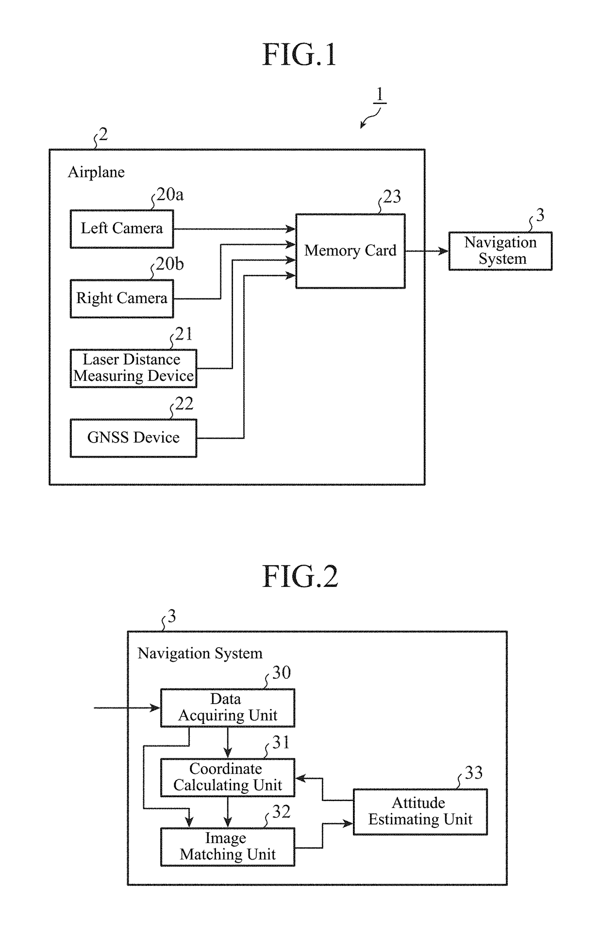
[0044]FIG. 1 is a block diagram showing the configuration of a survey system 1 according to Embodiment 1 of the present invention. The survey system 1 surveys geographical features from an airplane 2, and includes a left camera 20a, a right camera 20b, a laser distance measuring device 21, a GNSS device 22 and a memory card 23 which are mounted in the airplane 2, and a navigation system 3. The navigation system 3 estimates the attitude of the airplane 2 in flight, and, as shown in FIG. 1, is disposed separately from the airplane 2. Alternatively, the navigation system 3 may be mounted in the airplane 2. Further, the attitude of the airplane 2 is specified by the following three parameters: a roll angle ω, a pitch angle ϕ and a yaw angle κ which are attitude angles in a rolling direction, in a pitching direction and in a yawing direction of the airplane 2.

[0045]The airplane 2 is an embodiment of a moving body described in the present invention, and can fly with the left c...

Example

Embodiment 2

[0171]FIG. 23 is a block diagram showing the configuration of a survey system 1A according to Embodiment 2 of the present invention. The survey system 1A surveys geographical features from an airplane2A, and includes a left camera 20a, a right camera 20b, a laser distance measuring device 21, a GNSS device 22 and a wireless communication device 24 which are mounted in the airplane 2A, and a navigation system 3.

[0172]The wireless communication device 24 transmits distance data, angle data, coordinate data and image data which are acquired during a flight of the airplane 2A to the navigation system 3.

[0173]The navigation system 3 is provided separately from the airplane 2A, as shown in FIG. 23. As an alternative, the navigation system 3 can be mounted in the airplane 2A.

[0174]A data acquiring unit 30 of the navigation system 3 receives and acquires the distance data, the angle data, the coordinate data and the image data which are transmitted by the wireless communication ...


PUM


Abstract

Image matching on a pair of image data about images which are shot at different shooting positions is performed, and a point corresponding to the coordinates of a distance measurement point on the image shown by one image data of the pair is searched through the image shown by the other image data of the pair. The value of a parameter showing the attitude of an airplane (2) is corrected in such a way that the difference between the coordinates of the distance measurement point on the image shown by the other image data of the pair and the coordinates of the corresponding point which is searched for via the image matching becomes small, to estimate the attitude of the airplane (2).

Description

TECHNICAL FIELD[0001]The present invention relates to a navigation system that estimates the attitude of a moving body in which a camera for surveys and a laser distance measuring device are mounted, and a survey system provided with this navigation system.BACKGROUND ART[0002]Patent Literature 1, for example, discloses a survey system that performs photographic surveying and airborne laser scanning by using a camera and a laser emitting and receiving device which are mounted in a flying body.[0003]In this survey system, the camera that shoots a survey target from the flying body is supported by an attitude stabilizing device called a stabilizer, and the shooting direction can be kept aligned with a vertically downward direction regardless of the attitude of the flying body in flight.[0004]Further, the laser emitting and receiving device projects laser light to a survey target from the flying body at a predetermined period, and receives light reflected from this survey target. A cont...

Claims


Application Information

Patent Timeline
IPC IPC(8): G01C11/06B64D47/08G06T7/70H04N7/18G01B11/00G01S17/89G01S17/86
CPCG01C11/06B64D47/08G06T7/70H04N7/185G01B11/002G01S17/89G01C1/04G06T2207/10032G06T2207/30244G06T7/593G01S17/42G01S17/86G05D1/08
Inventor MAEHARA, HIDEAKINAGASE, MOMOYOTAIRA, KENJIKATO, SUMIO
Owner MITSUBISHI ELECTRIC CORP
Why Eureka
Try Eureka