Method for manufacturing r-t-b based sintered magnet
- Summary
- Abstract
- Description
- Claims
- Application Information
AI Technical Summary
Benefits of technology
Problems solved by technology
Method used
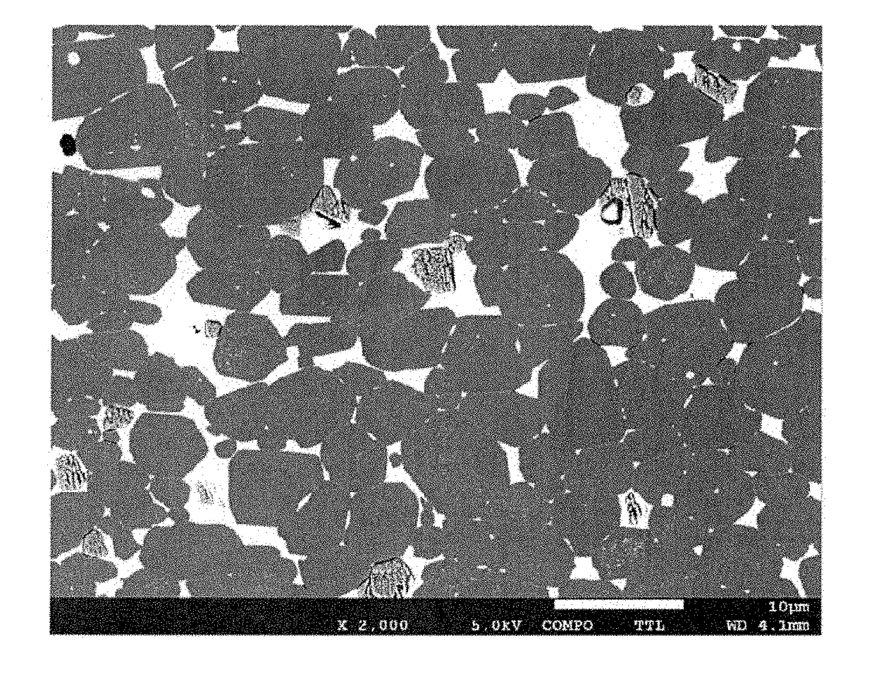
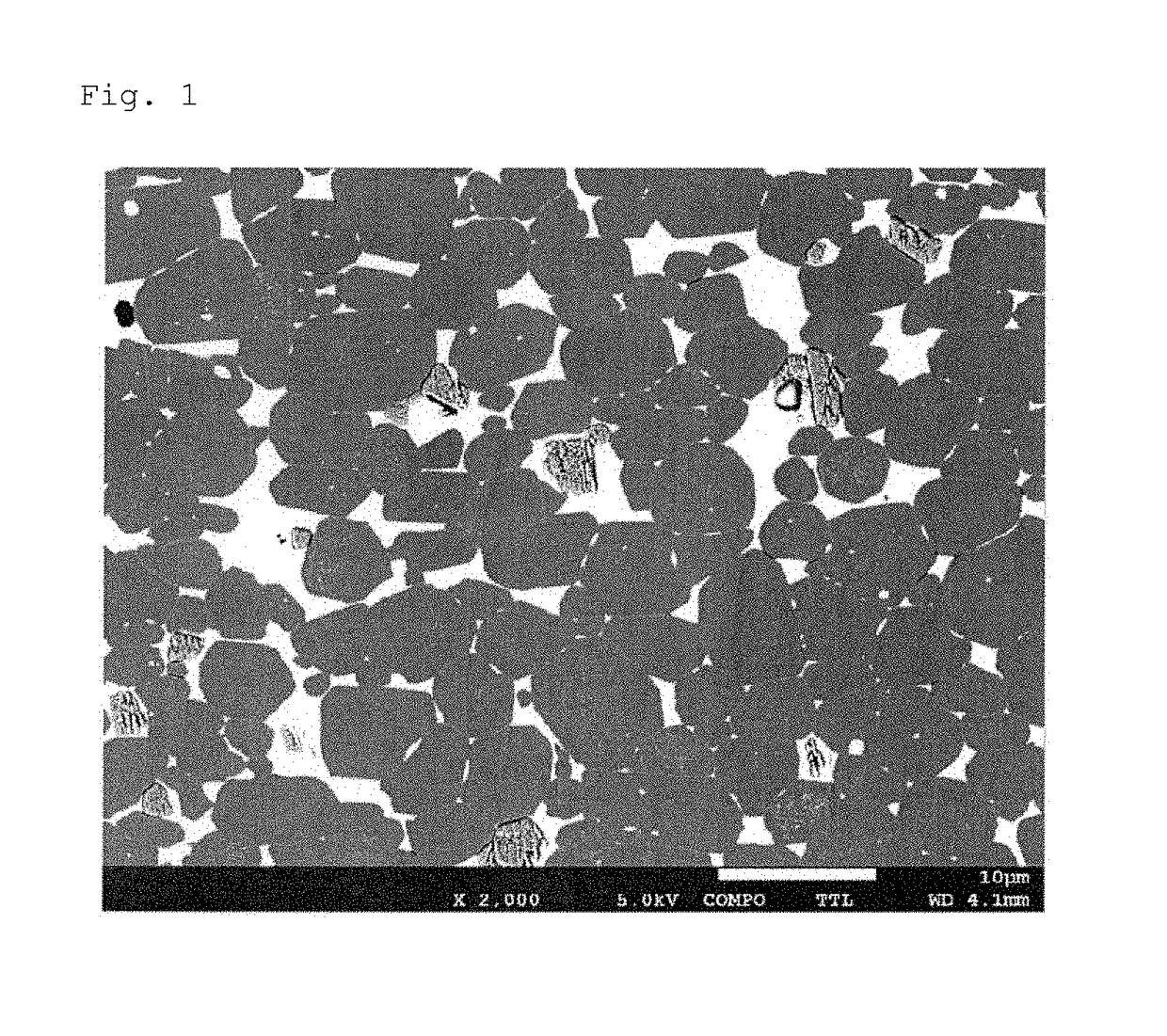
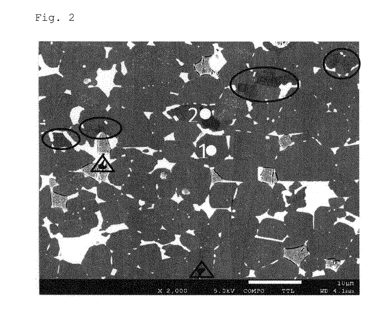
Image

Examples
example 1
n which a Molded Body was Sintered at a Temperature of 1,000° C. or Higher and 1,100° C. or Lower and (Condition a) was Performed and, after Cooling to Room Temperature, a Heat Treatment Step was Performed
[0082]After weighing raw materials of each element so as to have the composition (composition range of the present invention) shown in Table 1, an alloy was fabricated by a strip casting method. The alloy thus obtained was subjected to hydrogen grinding to obtain a coarse ground powder. Then, 0.04% by mass of a zinc stearate was added as a lubricant and mixed into 100% by mass of the coarse ground powder, followed by dry pulverization under a nitrogen gas flow using a jet mill device to obtain a fine pulverized powder (alloy powder) having a grain size D50 of 4 μm. Then, 0.05% by mass of zinc stearate was added as a lubricant and mixed into 100% by mass of the fine pulverized powder, followed by molding under a magnetic field to obtain a molded body. A molding device was a so-calle...
example 2
n which a Molded Body was Sintered at a Temperature of 1,000° C. or Higher and 1,100° C. or Lower and (Condition a) was Performed, and then a Heat Treatment Step was Continuously Performed from a Cooling Temperature of the (Condition a)
[0085]An R-T-B based sintered magnet was obtained under the same conditions as in Example 1 (the composition is also the same as in Table 1), except that sintering and the heat treatment were performed under the conditions shown in Table 4. The specimen No. 20 in Table 4 is a specimen obtained by sintering a molded body at 1,065° C., performing temperature dropping from 1,065° C. to 400° C. at an average cooling rate of 3° C. / min, and performing a second heat treatment by continuously heating from 400° C. to 700° C. (without cooling to room temperature), followed by cooling from 700° C. to 400° C. at an average cooling rate of 50° C. / min and further cooling from 400° C. to room temperature (cooling at an average cooling rate of 10° C. / min, the same sh...
example 3
n which a Molded Body was Sintered at a Temperature of 1,000° C. or Higher and 1,100° C. or Lower and (Condition b) was Performed and, after Cooling to Room Temperature, a Heat Treatment Step was Performed
[0088]An R-T-B based sintered magnet was obtained under the same conditions as in Example 1 (the composition is also the same as in Table 1), except that sintering and the heat treatment were performed under the conditions shown in Table 6. As for the specimen No. 24 in Table 6, an R-T-B based sintered magnet material was fabricated by sintering a molded body at 1,065° C., cooling to room temperature (cooling at an average cooling rate of 10° C. / min, the same shall apply to the specimens Nos. 25 to 46) and performing a first heat treatment by heating to 800° C., followed by cooling from 800° C. to 500° C. at an average cooling rate of 3° C. / min and further cooling from 500° C. to room temperature (cooling at an average cooling rate of 10° C. / min, the same shall apply to the specime...
PUM
| Property | Measurement | Unit |
|---|---|---|
| Temperature | aaaaa | aaaaa |
| Temperature | aaaaa | aaaaa |
| Temperature | aaaaa | aaaaa |
Abstract
Description
Claims
Application Information