Multi-layered safety system

a safety system and multi-layer technology, applied in semiconductor lasers, instruments, reradiation, etc., can solve problems such as difficulty in detecting objects before they enter the beam, and achieve the effect of improving the laser power beaming system

Active Publication Date: 2018-05-10
LASERMOTIVE
View PDF2 Cites 51 Cited by
  • Summary
  • Abstract
  • Description
  • Claims
  • Application Information

AI Technical Summary

Benefits of technology

[0051]The terms “impinge,”“impinge on,” and the like, as used in the present disclosure, may be understood to include a physical impact, an obstruction in a line of sight path, an interference with, an encroachment of, and to have an effect upon. Accordingly, physical contact or direct obstruction is not required for one element to impinge on another. Instead, a first element may impinge on a second element if the first element is detected or determined to have an actual or imminent effect on the second element, even if the first element is only near the second element. A non-exhaustive list of words that may interchangeably be used in addition to, in place of, or to better understand any of the grammatical forms of the word “impinge” include, as the context directs: obstruct, encroach, touch, trespass, invade, impede, enter, impose, interfere, intrude, violate, accroach, and obtrude.
[0052]In many cases, the flux (W/m2) in an optical high-flux power beam is substantially above the safe limit for exposure to living tissue such as a human or animal eye. In some cases, the flux is high e...

Problems solved by technology

Shutting off the beam before anything can enter it is one general way to overco...

Method used


Image

  • Multi-layered safety system
  • Multi-layered safety system
  • Multi-layered safety system

Examples


Embodiment Construction

[0044]The present application is related to the following applications filed on the same day as the present application, naming the same inventors, and assigned to the same entity; each of said applications incorporated herein by reference to the fullest extent allowed by law: U.S. patent application Ser. No. ______, entitled LIGHT CURTAIN SAFETY SYSTEM, bearing client number 720173.406; U.S. patent application Ser. No. ______, entitled DIFFUSION SAFETY SYSTEM, bearing client number 720173.407; U.S. patent application Ser. No. ______, entitled POWER BEAMING VCSEL ARRANGEMENT, bearing client number 720173.408; U.S. patent application Ser. No. ______, entitled LOCATING POWER RECEIVERS, bearing client number 720173.409; U.S. patent application Ser. No. ______, entitled MULTISTAGE WIRELESS POWER, bearing client number 720173.410.

[0045]The following description, along with the accompanying drawings, sets forth certain specific details in order to provide a thorough understanding of vario...


PUM


Abstract

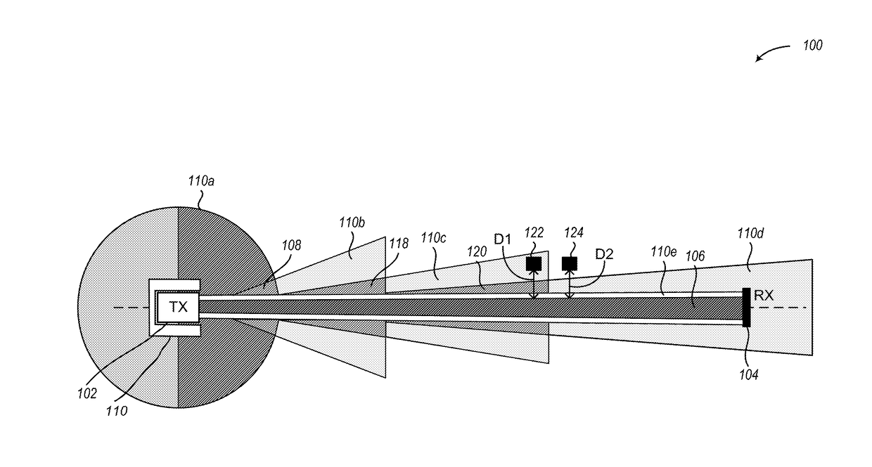
Embodiments are directed towards a safety system that can be used with a high-flux power beam, such as in wireless power transmission. The system includes a transmitter that generates and transmits a power beam and a receiver that receives the power beam. A plurality of sensors is configured to independently detect if an object is near, impeding, or about to impede (i.e., impinging) the power beam. Each of the plurality of sensors is configured to detect the object at different distances between the transmitter and the receiver. A controller triggers the transmitter to stop generating the power beam when any one or more of the plurality of sensors detects the object or a combination of the plurality of sensors detects the object. The controller triggers the transmitter to re-generate and transmit the power beam when each of the plurality of sensors fails to detect the object.

Description

CROSS-REFERENCE TO RELATED APPLICATION[0001]This application claims the benefit under 35 U.S.C. § 119(e) of U.S. Provisional Patent Application No. 62 / 163,307, filed on May 18, 2015, entitled “Provisional Patents for Wireless Power” which is hereby incorporated by reference in its entirety.BACKGROUNDTechnical Field[0002]The present disclosure generally relates to systems and methods to detect objects that are impeding or about to impede (i.e., impinging on) a high-flux power beam, and more particularly, but not exclusively to, a plurality of safety systems working cooperatively with one another to detect objects and interrupt transmission of the high-flux power beam.Description of the Related Art[0003]Wireless delivery of power is of utility for many applications, including unmanned aerial vehicles and personal electronic devices such as laptops and smartphones. Power beaming directs focused electromagnetic power, most often laser light, from a transmitter to a receiver in order to ...

Claims


Application Information

Patent Timeline
IPC IPC(8): H04B10/80H04B10/114G01S7/00G01S7/484H01S5/00H01S5/062H01S5/42G01S17/02G01S17/04G01S17/87G01S17/89
CPCH04B10/807H04B10/1141G01S7/006G01S7/484H01S5/0085H01S5/06216H01S5/423G01S17/026G01S17/88H02J50/30H02J50/60G01S17/87H01S5/005G01S17/04Y02E10/52G01S17/89G01V8/22G01S7/003H02J50/10H02J50/90G01S17/06
Inventor KARE, JORDIN T.NUGENT, JR., THOMAS J.BASHFORD, DAVIDERICKSON, CARSTEN CASEYBASHFORD, THOMAS W.
Owner LASERMOTIVE
Why Eureka
Try Eureka