Near eye wavefront emulating display

a display system and near eye technology, applied in the field of near eye display systems, can solve the problems of inability to provide a display system capable of overlaying high-resolution virtual content over the entire, inability to achieve the critical angle of waveguide material, and inability to achieve the practical use of this display system for ar applications

Active Publication Date: 2018-05-10
MANOR FINANCIAL INC
View PDF16 Cites 40 Cited by
  • Summary
  • Abstract
  • Description
  • Claims
  • Application Information

AI Technical Summary

Benefits of technology

[0013]The near eye display of the present invention employs a lens comprising a sparse array of emission points from which intensity modulated collimated light beams are emitted. Each beam represents an emulated wavefront emanative from a virtual object in the user's FOV. The beams are subsequently scanned by a second beam scanning layer in synchrony with the intensity modulation, over a range of angles covering a portion of the user's field of view to form an image tile. Each beam emission point and coupled scanning element is referred to herein as a “Pinbeam.” Critically, the projected active area of each Pinbeam and interspacing of the Pinbeam array, is restricted in size using the method disclosed, to eliminate optical aberrations of transmitted ambient light based on the photopic response limitations of the human eye.
[0015]The application of a Pinbeam array across a display lens, filling the space between the eyewear frames, ensures the FOV is constrained only by the eyewear itself. The lack of complex bulky optics supports a display integration into an enclosure having a comfortable form factor typical of standard eye glasses. In another embodiment a curved lens with disposed Pinbeam array may be employed to extend the FOV beyond standard eye glasses form factor. In another embodiment, adjacent Pinbeams are configured to emit light beams at redundant angles to yield an expanded exit pupil.
[0016]The use of a remote modulated light source array in the preferred embodiment provides an efficient means of offloading image processing from the head-worn frames housing the display lens. In another embodiment, the light source array is a micro-emitter array, such as a mirco-LED or micro-LCD array embedder in the eyewear itself to support an untethered configuration. In another embodiment, an offset is introduced into the light intensity modulation signal of a redundant Pinbeam to support emulation of a curved wavefront, hence the presentation of virtual content intended to appear at a distance closer than optical infinity to the user.
[0017]In another embodiment, the present invention employs foveated imaging to minimize the resolution required per Pinbeam element, hence the entire display system.

Problems solved by technology

However, while many advancements have been made, prior art has failed to provide a display system capable of overlaying high resolution virtual content over the entire range of a user's natural Field of View (FOV) while maintaining a comfortable form factor.
As described in U.S. patent application Ser. No. 13 / 426,379 entitled “Increasing Field of View of Reflective Waveguide” to Robbins et al., the field of view of systems that rely solely on waveguide material properties is inherently limited by the waveguide material critical angle.
However, the requirement for intermediary projection optic resulting in an image that converges on the eye pupil, in conjunction with the bulky system architecture near the user's line of sight precludes the practical use of this display for AR applications.
However, the architecture requires a dense array of embedded addressable emission points with coupled collimating optics, the presence of which, without costly compensation unaddressed in the art, result in optical aberrations of transmitted ambient light.
Thus, while suitable for occluded displays, the architecture precludes its application in near eye optical see-through displays.
Similar to Sprague's architecture, the requirement for diffractive components of a SLM in the user's line of sight results in unsatisfactory optical aberrations of transmitted light such as double images and rainbow patterns.
Thus, the application of a stereoscopic pair to present a virtual image of a nearby object without concurrently emulating the natural curvature of the incident wavefront leads to an accommodation-vergence conflict that can be the source of physical discomfort for users and diminishes the realism of displayed 3D content due to the lack of accommodative depth cues.

Method used


Image

  • Near eye wavefront emulating display
  • Near eye wavefront emulating display
  • Near eye wavefront emulating display

Examples


Embodiment Construction

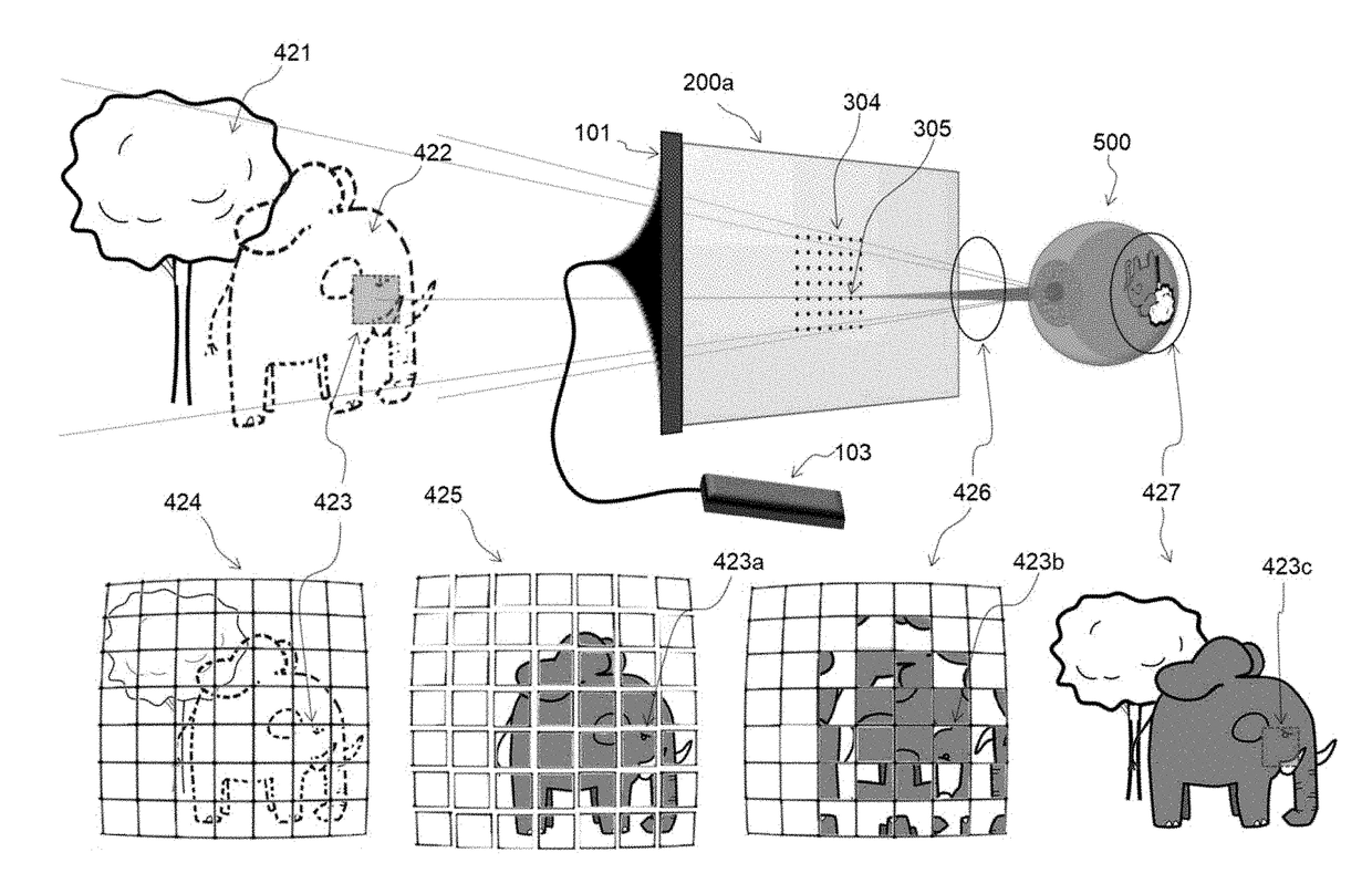
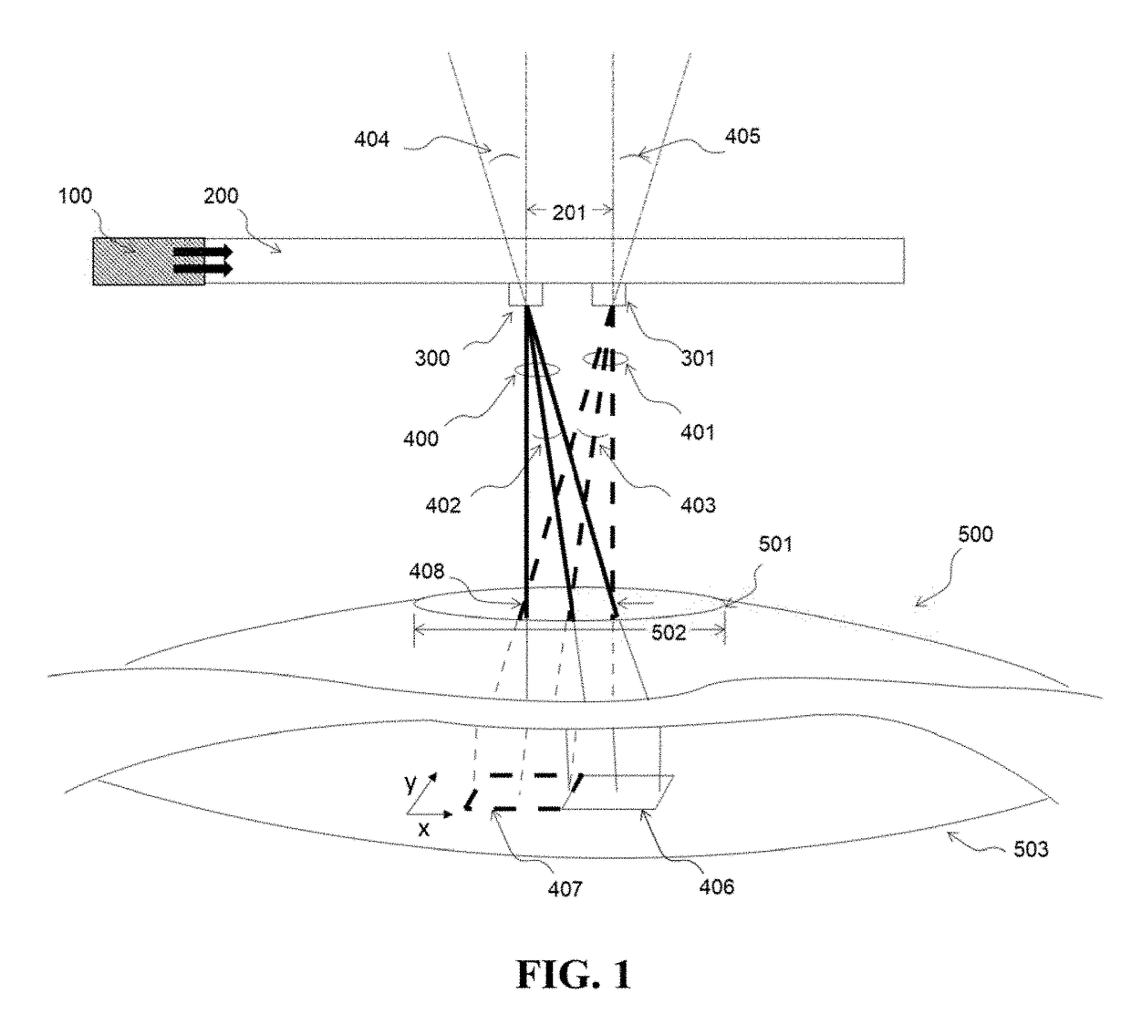
[0039]A system providing a near-eye display for augmented and virtual reality imaging is described. Referring to the figures, wherein like numerals indicate like or corresponding parts throughout the several views, a near eye display lens 200 is supplied with image forming information transmitted from an image signal generating element 100 attached to the edge of the display lens. The lens is generally placed in front of an exemplary human eye 500 as shown in cross-sectional view of FIG. 1. For simplicity, the middle section of the eye has been removed, but it is understood that light rays transmitted through the eye pupil 501, also pass through and are optically redirected by the lens of the eye. The image signal is comprised on precise temporal (i.e. light intensity pulsing) and spatial (i.e. light directional scanning) modulation necessary for light transmitted through the lens from a collimated light emitting element (not shown) to form an image on the eye retina 503. The collim...


PUM


Abstract

A near eye display device includes a sparse array of intensity modulated light beam emission and steering points disposed on a transparent lens, capable of forming a wide field of view composite image directly on the retina with variable degrees of apparent depth controlled by an image forming timing signal. The active regions of the beam emission and steering elements is configured so as not to generate optical aberrations of transmitted ambient light that is apparent to the eye. The display may be applied to small form factor stereoscopic head worn display systems and used in conjunction with Augmented Reality software applications.

Description

CROSS REFERENCE TO RELATED APPLICATIONS[0001]This application claims priority from U.S. Provisional Application No. 62 / 420,519 filed Nov. 10, 2016, entitled “NEAR EYE WAVEFRONT EMULATING DISPLAY.” The content of the aforementioned application is hereby expressly incorporated by reference into the present application in its entirety.FIELD OF THE INVENTION[0002]The invention relates generally to near-eye display systems, more specifically to optical see-through Virtual Retinal Display (VRD) systems for Augmented Reality.BACKGROUND OF THE INVENTION[0003]Head mounted optical see-through displays are a class of device that enable the visual Augmented Reality, referred to herein simply as Augmented Reality (AR). AR is a mode of Human Computer Interaction in which virtual content is overlaid in real-time onto a user's perception of the real environment such that the virtual content appears to be physically present in a scene. However, while many advancements have been made, prior art has f...

Claims


Application Information

Patent Timeline
Patent Type & Authority Applications(United States)
IPC IPC(8): H04N13/04G02B27/01G02B26/10H04N9/31H04N13/00
CPCH04N13/122H04N13/383H04N13/344H04N13/044G02B27/0172G02B26/10H04N13/0018H04N9/3188G02B2027/0134H04N9/3129H04N13/0484G02B2027/0125G02B2027/0178G02B26/106
Inventor SHANKS, MARKKEMENDO, ANDREW
Owner MANOR FINANCIAL INC
Why Eureka
Try Eureka