
Preparative chromatograph

a chromatograph and chromatograph technology, applied in the field of chromatographs, can solve the problems of delay time becoming inaccurate, cross-sectional area, etc., and the influence of pipe diameter error within the range of tolerances, so as to suppress delay time error and diffusion of target components, shorten the pipe length, and shorten the second pipe length

Inactive Publication Date: 2018-05-17
SHIMADZU CORP
View PDF1 Cites 2 Cited by
  • Summary
  • Abstract
  • Description
  • Claims
  • Application Information

AI Technical Summary

Benefits of technology

The present invention provides a preparative chromatograph that improves the collection of target components by reducing the error of delay time and diffusion of components in the pipe. This is achieved by shortening the length of the second pipe connecting the flow cell and the flow path switching unit, which makes the delay time more accurate and ensures better collection of target components. The flow cell and the flow path switching unit are mounted on the fractionation head, which eliminates the need to consider the movement of the fractionation head and further shortens the second pipe. The preparative chromatographs disclosed herein may be implemented with shortened pipe length from the flow cell to the flow path switching unit, which suppresses the delay time error and diffusion of target components.

Problems solved by technology

However, a diameter, a cross-sectional area, etc., of a pipe have manufacturing errors within a range of tolerance.
Since the delay time is calculated based on a pipe capacity determined by the product of the diameter (cross-sectional area) of the pipe and the length of the pipe, the longer the pipe is, the larger the influence of the error of the pipe diameter becomes, so that the delay time becomes inaccurate.
As a result, there was a problem that the preparation was started even though the target component has not yet reached sufficiently or the preparation was terminated even though the peak of the target component was still continuing.
For this reason, depending on the arrangement of these housings, the length of the pipe connecting them became long, which increased the error of the delay time and the diffusion of the components in the pipe.
For this reason, it is necessary to use a spectroscopic unit including a diffraction grating for extracting light of a desired wavelength and a motor for driving the diffraction grating, and therefore it was difficult to accommodate the entire absorption spectrophotometer within the housing of the fraction collector.
On the other hand, when an LED light source with a narrow range of an emission wavelength is used, the spectroscopic unit (a diffraction grating and a motor) becomes unnecessary.

Method used


Image

  • Preparative chromatograph
  • Preparative chromatograph
  • Preparative chromatograph

Examples


Embodiment Construction

[0030]Examples of a preparative chromatograph according to exemplary embodiments of the present invention will be described below with reference to drawings.

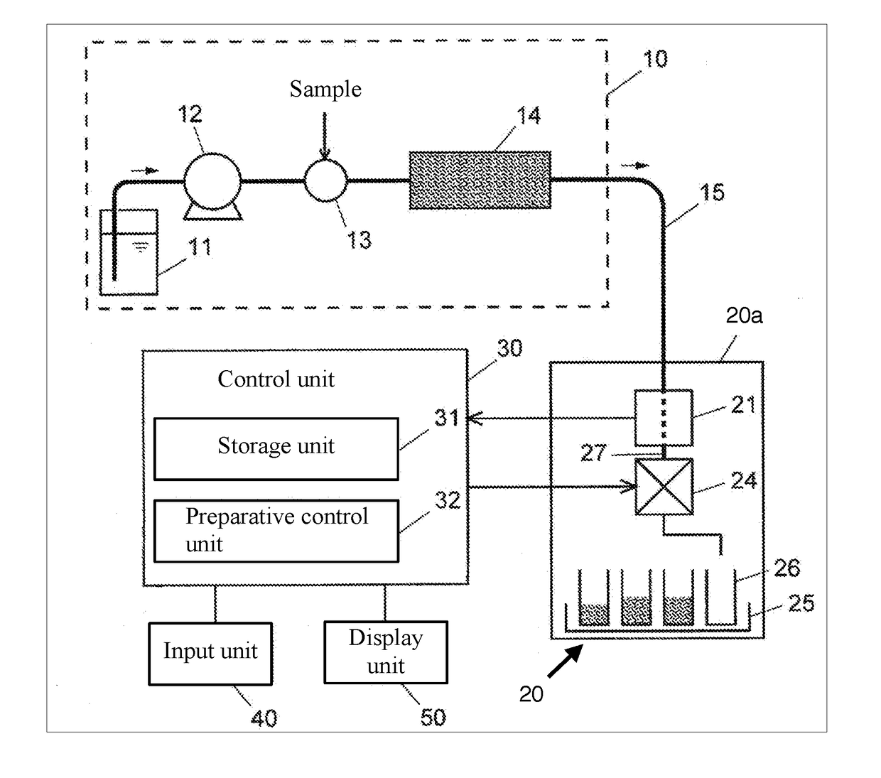
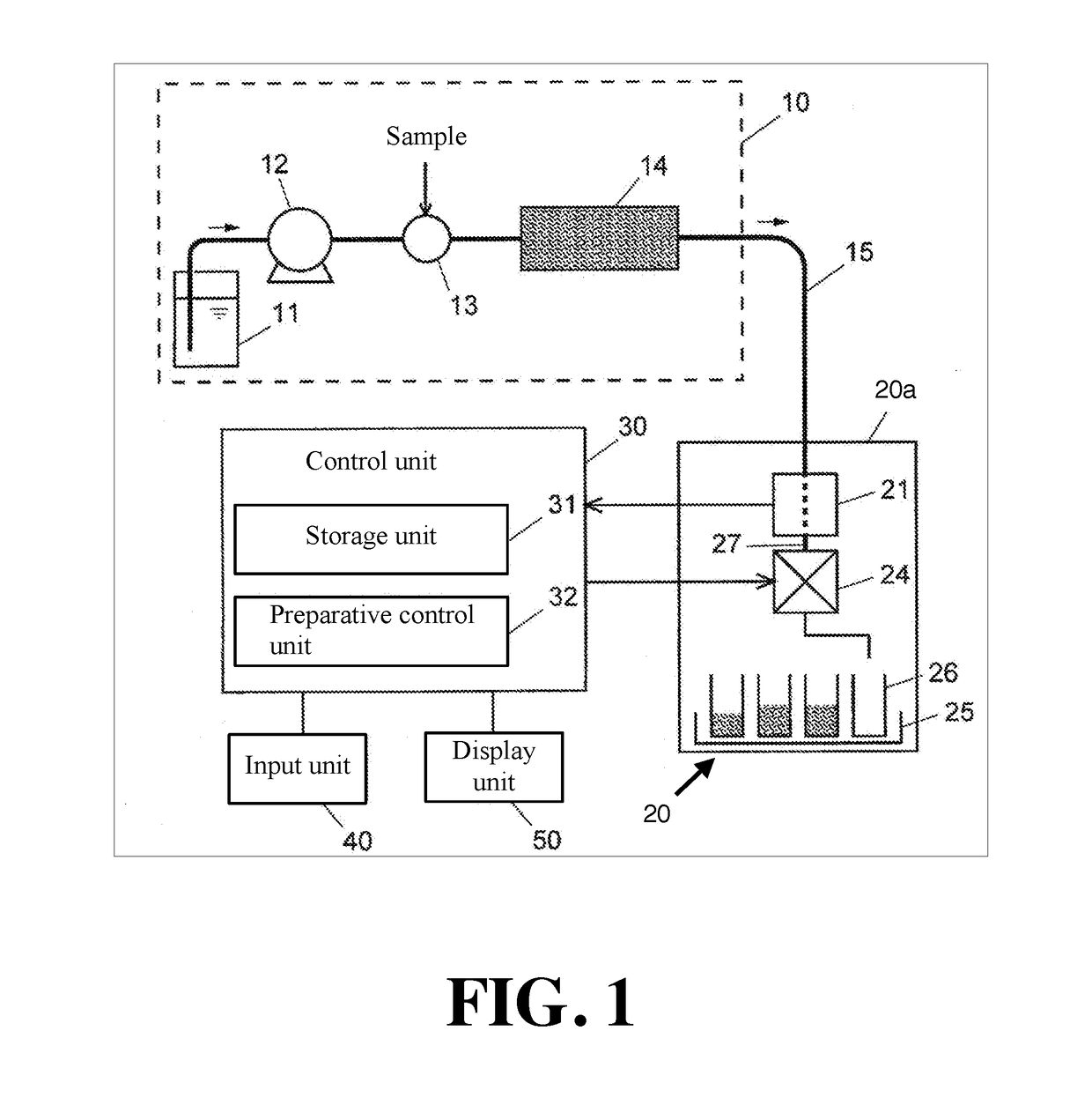
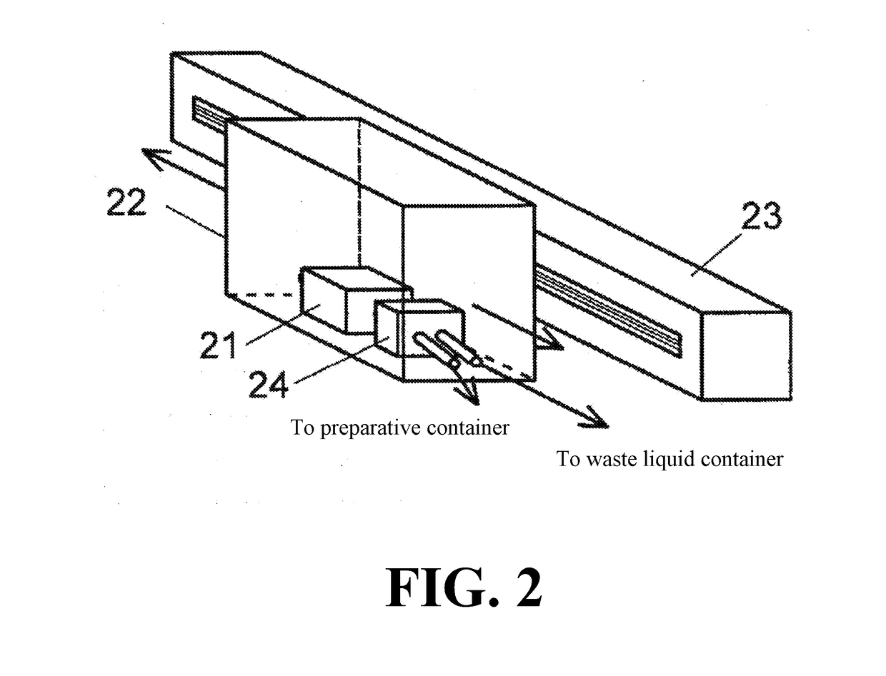
[0031]FIG. 1 shows a configuration of a main portion of a preparative chromatograph of this example. FIG. 2 shows a configuration of a main portion of a fraction collector 20 of the preparative chromatograph. The preparative liquid chromatograph of this example is roughly composed of a liquid chromatograph unit 10 for separating target components contained in a sample, a fraction collector 20 for collecting the target components separated by the liquid chromatograph unit 10, and a control unit 30 for controlling operations of these devices.

[0032]In the liquid chromatograph unit 10, a mobile phase in a mobile phase container 11 is sucked up by a liquid supply pump 12 and fed to a column 14 at a predetermined flow rate. A sample containing the target component is injected at a sample injection unit 13 and transported to the column...


PUM


Abstract

A preparative chromatograph for collecting target components in a sample temporally separated in a column of a chromatograph in respective preparative containers is provided with: a detection unit having a flow cell accommodated in a housing and a detector for detecting a component that passes through the flow cell; a first pipe that connects the column and an inlet end of the flow cell; a flow path switching unit accommodated in the housing and configured to selectively flow the components that passed through the flow cell through a preparative flow path that is a flow path connected to the preparative containers or a waste liquid flow path; and a second pipe accommodated in the housing and connecting an outlet end of the flow cell and the flow path switching unit.

Description

TECHNICAL FIELD[0001]The present invention relates to a preparative chromatograph for collecting target components separated in a column of a liquid chromatograph by a fraction collector.BACKGROUND ART[0002]A preparative chromatograph is composed of a liquid chromatograph unit, a detector and a fraction collector arranged at a subsequent stage of the liquid chromatograph, and a control unit for controlling operations of the aforementioned devices. In the preparative chromatograph, components in a sample temporally separated and eluted in a column of the liquid chromatograph unit are detected when the components pass through the detector and introduced into a fraction collector to be collected in preparative containers (see, for example, Patent Document Nos. 1 and 2).[0003]The liquid chromatograph unit is composed of, for example, a liquid supply pump, a sample injection unit, a column, etc. The components eluted from the column are introduced into a flow cell of a detector such as a...

Claims


Application Information

Patent Timeline
IPC IPC(8): G01N30/38G01N30/74G01N30/82G01N30/84
CPCG01N30/38G01N30/74G01N30/82G01N30/84G01N2030/382B01D15/08
Inventor NAKAMURA, TAKAFUMIYAMAGUCHI, TADAYUKINAGAI, YUSUKE
Owner SHIMADZU CORP
Learn More