
SiN SPACER PROFILE PATTERNING

a spacer and profile technology, applied in the field of semiconductor/solid-state device manufacturing, basic electric elements, electrical equipment, etc., can solve the problems of deformation of remaining materials, deformation of wet processes, and damage to local plasmas, so as to reduce pitch walking and reduce thickness

Active Publication Date: 2018-05-17
APPLIED MATERIALS INC
View PDF0 Cites 98 Cited by
  • Summary
  • Abstract
  • Description
  • Claims
  • Application Information

AI Technical Summary

Benefits of technology

The patent text describes methods for processing semiconductor substrates to form recesses and remove silicon oxide materials. The methods involve using plasmas to modify the surface of the substrate, including the oxidation of exposed silicon nitride surfaces and the formation of silicon oxide regions. The methods may be performed in a single semiconductor processing chamber and may use remote plasmas or fluorine-containing precursors for the modification and etching processes. The technical effects of the methods include improved surface quality and selectivity in removing silicon oxide materials.

Problems solved by technology

However, wet processes may have difficulty penetrating some constrained trenches and also may sometimes deform the remaining material.
However, local plasmas may damage the substrate through the production of electric arcs as they discharge.

Method used


Image

  • SiN SPACER PROFILE PATTERNING
  • SiN SPACER PROFILE PATTERNING
  • SiN SPACER PROFILE PATTERNING

Examples


Embodiment Construction

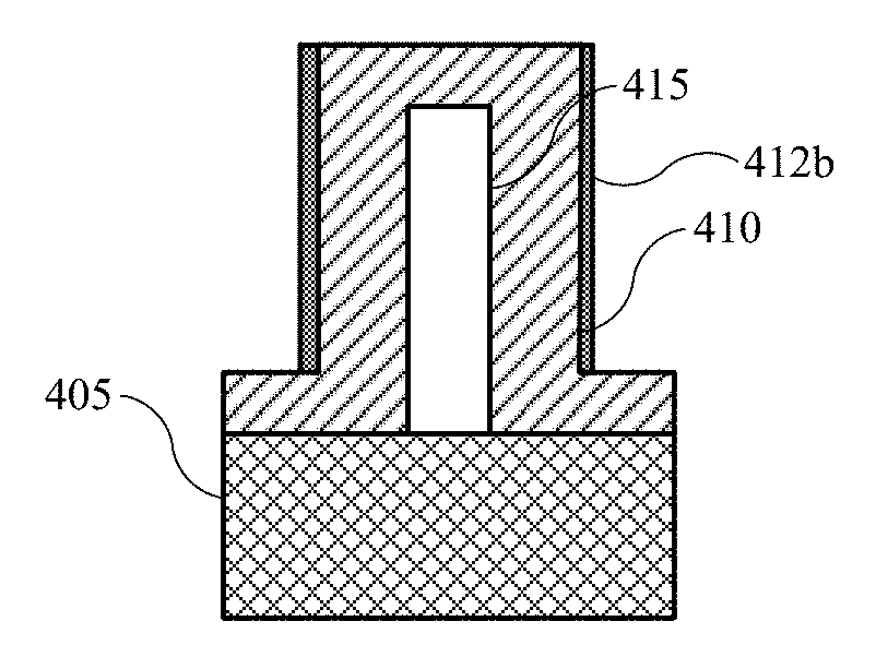
[0021]The present technology includes systems and components for semiconductor processing of small pitch features. As line pitch is reduced, standard lithography processes may be limited, and alternative mechanisms may be used in patterning. During one such patterning operation, nitride spacers may be formed over an oxide surface. In one formation scenario, the nitride layer is deposited over dummy polysilicon lines and over a pad oxide. To form the nitride spacers, an etching process is performed that may remove the continuity of the nitride layer as well as the polysilicon. However, the nitride deposited may have rounded corners that may become more pronounced and even fully taper during the etching operation. This extra gap-side etching may cause the line thickness between the cores and gaps to differ, which may cause pitch walking in later processes.

[0022]Conventional technologies may include extreme ultraviolet lithography or self-aligned double or quadruple patterning to produ...


PUM


Abstract

Processing methods may be performed to form recesses in a semiconductor substrate. The methods may include oxidizing an exposed silicon nitride surface on a semiconductor substrate within a processing region of a semiconductor processing chamber. The methods may include forming an inert plasma within the processing region of the processing chamber. Effluents of the inert plasma may be utilized to modify the oxidized silicon nitride. A remote plasma may be formed from a fluorine-containing precursor to produce plasma effluents. The methods may include flowing the plasma effluents to the processing region of the semiconductor processing chamber. The methods may also include removing the modified oxidized silicon nitride from the semiconductor substrate.

Description

TECHNICAL FIELD[0001]The present technology relates to semiconductor systems, processes, and equipment. More specifically, the present technology relates to systems and methods for removing oxidized material from a semiconductor substrate.BACKGROUND[0002]Integrated circuits are made possible by processes which produce intricately patterned material layers on substrate surfaces. Producing patterned material on a substrate requires controlled methods for removal of exposed material. Chemical etching is used for a variety of purposes including transferring a pattern in photoresist into underlying layers, thinning layers, or thinning lateral dimensions of features already present on the surface. Often it is desirable to have an etch process that etches one material faster than another facilitating, for example, a pattern transfer process. Such an etch process is said to be selective to the first material. As a result of the diversity of materials, circuits, and processes, etch processes...

Claims


Application Information

Patent Timeline
IPC IPC(8): H01L21/311H01L21/02
CPCH01L21/31116H01L21/0217H01L21/02164H01L21/0223H01L21/0337H01L21/31144H01L21/3105H01L21/3115H01L21/0234H01L21/02326
Inventor KO, JUNGMINCHOI, TOMINGLE, NITINKIM, KWANG-SOOWOU, THEODORE
Owner APPLIED MATERIALS INC
Learn More