Contact-via chain as corrosion detector

Active Publication Date: 2018-05-17
ROBERT BOSCH GMBH
View PDF3 Cites 4 Cited by
  • Summary
  • Abstract
  • Description
  • Claims
  • Application Information

AI Technical Summary

Benefits of technology

[0012]The advantage in this respect is that it is possible to check the guard ring initially and in operation. In other words, a faulty semiconductor element is determined early and it is possible for the evaluation to occur variably at different points in time, either during the final product test or in situ in operation. It is furthermore advantageous that it is possible to detect an increased risk for a failure of the g

Problems solved by technology

U.S. Pat. No. 6,833,720 B1, on the other hand, is limit

Method used


Image

  • Contact-via chain as corrosion detector
  • Contact-via chain as corrosion detector
  • Contact-via chain as corrosion detector

Examples


Embodiment Construction

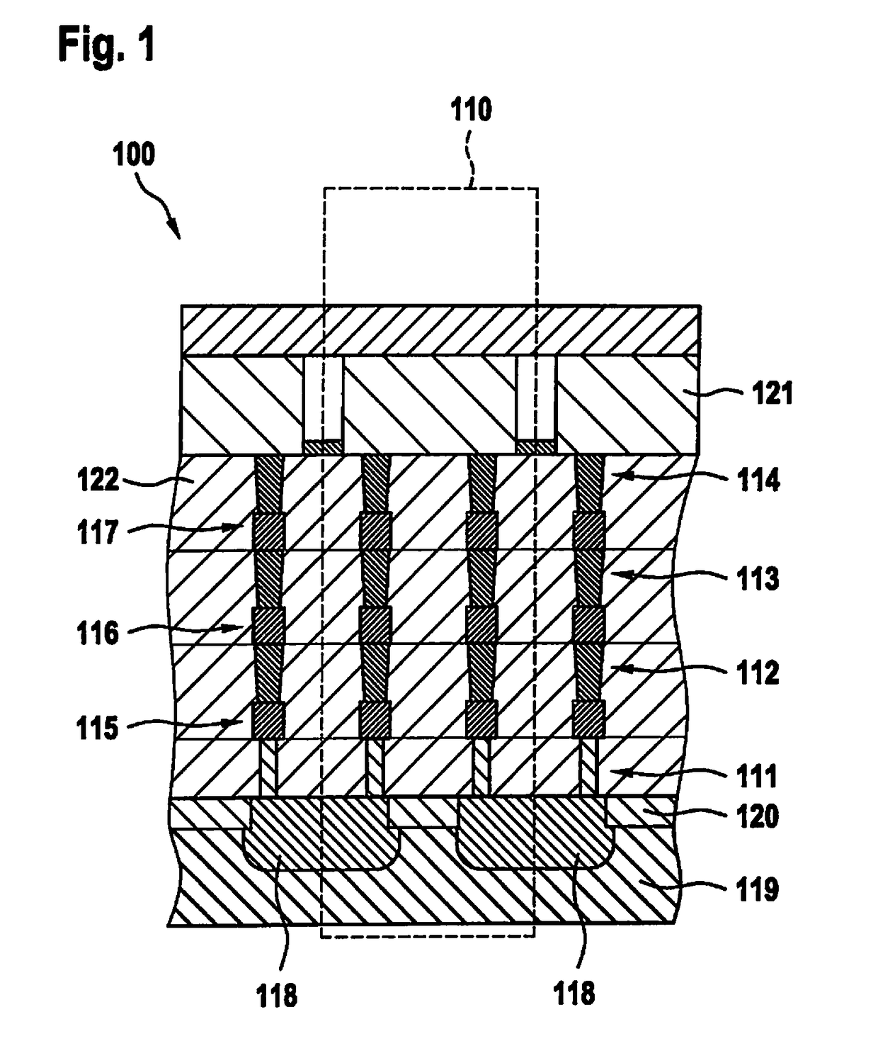
[0021]FIG. 1 shows cross section 100 of a basic element 110 of a complete contact-via chain. The basic element 110 or the structure comprises a combined interconnection of contacts 111, vias 112, 113 and 114, as well as metal segments 115, 116 and 117 and well resistors 118. In one development, the conductive path is run starting from a contact to the lowest metal or first metal segment 115, proceeding by way of a via 112 to the metal or second metal segment 116 lying thereabove and analogously up to the uppermost metal or terminating metal layer, e.g. top metal. From the uppermost metal or from the terminating metal layer, the basic element 110 of the contact-via chain is then guided back by way of vias 114, 113 and 112 and the metals 117, 116 and 115 lying therebetween to the contact level. The connection between two contacts occurs via a conductive diffused well, which is designed to be insulating vis-à-vis a substrate 119, for example an n-doped well in a p-doped substrate or vi...


PUM


Abstract

A detector for determining a faulty semiconductor component including a semiconductor component, a contact-via chain, which is situated laterally at a distance from the semiconductor component and which surrounds the semiconductor component in regions, a guard ring, which is situated laterally at a distance from the semiconductor component, and an evaluation unit, which is situated on the semiconductor component, wherein the evaluation unit is designed to apply an electrical voltage to the contact-via chain, in particular a permanent electrical voltage, to detect a resistance value of the contact-via chain and to produce an output signal when the resistance value of the contact-via chain exceeds a threshold value.

Description

BACKGROUND INFORMATION[0001]The present invention relates to a detector for determining faulty semiconductor components and to a method for detecting faulty semiconductor components. In other words, the present invention relates to a contact-via chain as a corrosion and crack detector.[0002]During their manufacture on a wafer, semiconductor components are separated by sawing trenches, which are used in the later assembly process for separation by sawing or other methods. The semiconductor elements are protected vis-à-vis these sawing trenches by a guard ring, the so-called scribe seal. The latter has the task both of stopping cracks caused by sawing the wafer as well as of preventing foreign molecules from diffusing into the circuit. The use of a guard ring is related art.[0003]In addition, there are various approaches of controlling the function of the guard ring. U.S. Pat. No. 6,833,720 B1 describes a contact-via chain as a detection unit that tests specifically for damages by the...

Claims


Application Information

Patent Timeline
IPC IPC(8): H01L21/66H01L23/522H01L23/58H01L23/528H01L23/00G01R31/26
CPCH01L22/34H01L23/5226H01L23/585H01L23/528H01L23/562G01R31/2607G01R31/2644
Inventor SCHNEIDER, DANIELDIETZ, FRANZ
Owner ROBERT BOSCH GMBH
Why Eureka
Try Eureka