Ion Filter

a technology of ion filter and filter plate, which is applied in the direction of particle separator tube details, electric discharge tubes, beam/ray focussing/reflecting arrangements, etc., can solve the problems of etching structure damage, lack of ideal ratio of ions to numbers, and production of plasma, so as to reduce the etch selectivity of the mask, reduce the erosion of the mask, and increase the bias of the aperture plate

Inactive Publication Date: 2018-05-24
PLASMA THERM
View PDF6 Cites 3 Cited by
  • Summary
  • Abstract
  • Description
  • Claims
  • Application Information

AI Technical Summary

Benefits of technology

[0020]In the Bosch DRIE process, anisotropic etching of features into the silicon as defined by a mask on the surface of the silicon takes place by repetition of an etch and deposition process cycle many times. As the process proceeds through one cycle, in the deposition step a passivation layer is deposited on all surfaces. At the start of the following etch step (or frequently defined as a first etch sub-step), ions from the plasma are accelerated to the wafer and remove the passivating material from the base of the feature being etched. In the remainder of the etch step (or the second etch sub-step) silicon is etched isotropically using the neutral radicals produced in the plasma. As the cycle is repeated the feature defined by the mask is etched further down into the silicon wafer. It is of particular importance to the effective operation of the process that in the first etch sub-step the ion flux is well defined in terms of a number of parameters, while in the second etch sub-step and in the deposition step the number of ions should be small as they do not contribute significantly to either step and can have the detrimental effect if in too great numbers to reducing the etch selectivity to the mask so that the mask is eroded too quickly and the feature ceases to be defined laterally before it has achieved sufficient depth.
[0021]In relation to the Bosch DRIE process it is desirable to increase aperture plate bias on the aperture plate or between aperture plates or sections of aperture plates, so that during the deposition step and second etch sub-step to reduce the number of ions reaching the wafer and so reduce the mask erosion, thereby increasing the selectivity of the overall process to the mask. The level of aperture plate bias would be reduced during the first etch sub-step so that sufficient numbers of ions can be accelerated to the wafer to achieve the required directional passivation removal. For an ion filter divided into annular aperture zones or into other aperture zone geometries, the bias applied to the driven aperture plate in each sector can be varied as appropriate to achieve a highly uniform ion density across the wafer during the first etch sub-step and also a very low number of ions to the wafer during the second etch sub-step and the deposition step. If the ion filter is not divided into a number of annular aperture zones, time varying bias may still be applied in the manner described in this invention for use with regard to the Bosch DRIE process or any other process that requires a time variation in the number of ions reaching the wafer.

Problems solved by technology

It is frequently the case that the plasma produced while being usable for the required purpose, does not have the ideal ratio of numbers of ions to numbers of chemically reactive radicals to achieve the most effective plasma processing of the wafer.
It is particularly the case as requirements become stronger to etch material at ever faster rates that simply increasing the flow of gas to the plasma source and the level of power used to dissociate and ionize the gas, results in a plasma where there are too many ions in relation to the number of neutral radicals and as the etching process proceeds the excess numbers of ions may cause damage to the structures being etched.
The magnet based techniques are limited in the pressure range where they may be used as with increasing pressure there is an increased probability that electrons will not remain trapped on the magnetic field lines because they suffer collisions with neutral gas atoms or molecules and randomly walk across the field lines.
At pressures above 10 to 20 mTorr, the technique becomes less effective.
Ion loss will be greater if the transparency of the grid is reduced.
As the aperture aspect ratio increases, charged species passing through an aperture have increased probability of contacting the side wall of the aperture and being lost.

Method used


Image

  • Ion Filter
  • Ion Filter
  • Ion Filter

Examples


Embodiment Construction

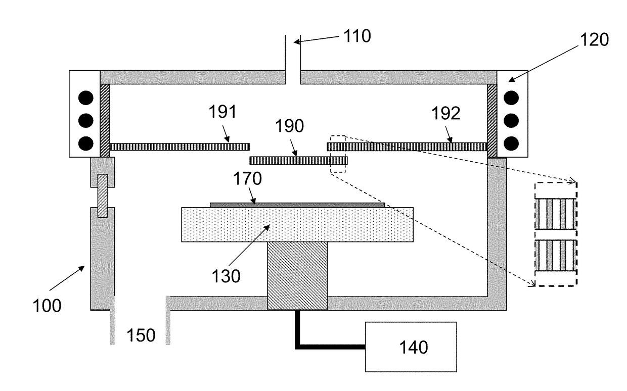
[0046]The present invention provides several method embodiments for using ion filtering to adjust the number of ions delivered to a substrate. All of the method embodiments of the present invention have a process chamber that is operatively connected to a plasma source wherein the substrate is placed on a substrate support that is provided within the process chamber. All of the method embodiments of the present invention can have the substrate further comprise a semiconductor wafer on tape on a frame. All of the method embodiments of the present invention generate a plasma using the plasma source that is used to process the substrate in the process chamber.

[0047]In all of the method embodiments described herein, when an aperture plate is divided into two or more physically separate zones that may be separately biased, it is possible by adjusting the bias voltage to a different level in the two or more aperture plate zones to adjust the degree of ion filtering to a greater or lesser ...


PUM


Abstract

The present invention provides a method for using ion filtering to adjust the number of ions delivered to a substrate. The method comprising a process chamber being provided that is operatively connected to a plasma source. The substrate is provided on a substrate support that is provided within the process chamber. An electrical bias source is provided that is operatively connected to an aperture plate that is provided in the process chamber. The substrate on the substrate support is processed using a plasma generated using the plasma source. A variable bias voltage from the electrical bias source is applied to the aperture plate during the plasma processing of the substrate. The plasma processing of the substrate can further comprise exposing the substrate to a plasma time division multiplex process which alternates between deposition and etching on the substrate.

Description

CROSS REFERENCES TO RELATED APPLICATIONS[0001]This application claims priority from and is related to commonly owned U.S. Provisional Patent Application Ser. No. 62 / 424,360 filed Nov. 18, 2016, entitled: ION FILTER, this Provisional Patent Application incorporated by reference herein.FIELD OF THE INVENTION[0002]Invention relates to the field of charged particle sources including plasma sources for direct etching and deposition, broad-beam ion sources for ion beam deposition and etching, and electron sources for surface modification.BACKGROUND OF THE INVENTION[0003]Plasma processing apparatus used to etch silicon wafers and other substrates or to deposit a variety of materials on to various substrates can be very effective for the production of semiconductor devices and other related systems. In its basic form, plasma is generated in a source region from appropriate precursor gases forming positive ions of the gas, electrons and neutral radicals. At the wafer, for an etch process, th...

Claims


Application Information

Patent Timeline
Patent Type & Authority Applications(United States)
IPC IPC(8): G01T1/28H01J49/02H01J3/14
CPCG01T1/28H01J49/02H01J3/14H01L21/78H01J37/32357H01J37/32422H01J37/32577H01J37/32633H01J37/32871
Inventor LEA, LESLIE MICHAELMARTINEZ, LINNELLMORGAN, MICHAELWESTERMAN, RUSSELL
Owner PLASMA THERM
Why Eureka
Try Eureka