Distributed feedback laser and preparation method thereof

A distributed feedback, laser technology, applied in the field of lasers, can solve the problems affecting laser performance and practical application, large aspect ratio of etched grating, mode instability, etc., to reduce the etching selection ratio, improve device performance, reduce The effect of preparation cost

Pending Publication Date: 2021-05-28
因林光电科技(苏州)有限公司
View PDF0 Cites 3 Cited by
  • Summary
  • Abstract
  • Description
  • Claims
  • Application Information

AI Technical Summary

Problems solved by technology

[0005] In view of this, the embodiment of the present invention provides a distributed feedback laser and its preparation method to solve the problems of high etching cost and high aspect ratio of the etched grating caused by the low-order grating structure in the prior art. The formation of a steep and smooth grating structure during the etching process and the use of high-order grating structures have multiple wavelength modes, resulting in unstable modes during operation, prone to mode hopping, and easy to change with changes in injection current and working environment, serious Technical issues affecting the performance and practical application of lasers

Method used


Image

  • Distributed feedback laser and preparation method thereof
  • Distributed feedback laser and preparation method thereof
  • Distributed feedback laser and preparation method thereof

Examples


Embodiment

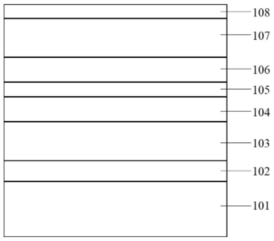
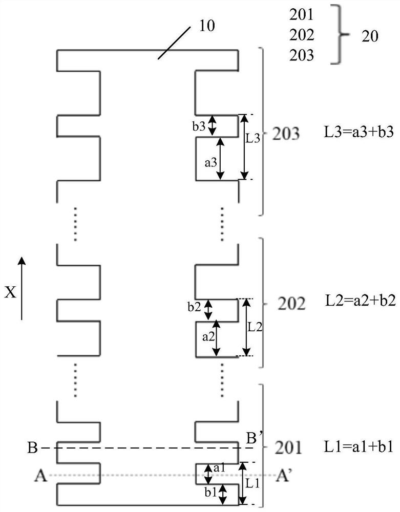
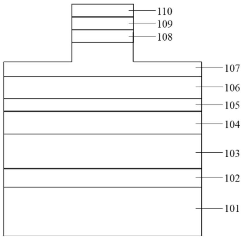
[0059] An embodiment of the present invention provides a distributed feedback laser. figure 1 A cross-sectional schematic diagram of an epitaxial structure of a distributed feedback laser provided by an embodiment of the present invention; figure 2 A surface schematic diagram of an epitaxial structure after a distributed feedback laser has etched a ridge structure and a grating structure group provided for an embodiment of the present invention; image 3 for figure 2 Schematic cross-sectional view of the ridge structure along the AA' direction in ; Figure 4 for figure 2 Schematic cross-sectional view of the grating structure group along the BB' direction in . Such as Figure 1-4 As shown, the distributed feedback laser includes: a laser epitaxial structure, the laser epitaxial structure includes a substrate 101 and a multi-layer epitaxial layer located on one side of the substrate 101, the multi-layer epitaxial layer includes an intermediate epitaxial layer and an inte...


PUM

PropertyMeasurementUnit
wavelengthaaaaaaaaaa
refractive indexaaaaaaaaaa

Abstract

The invention discloses a distributed feedback laser and a preparation method thereof. The distributed feedback laser comprises a laser epitaxial structure, a first electrode layer and a second electrode layer, wherein the laser epitaxial structure comprises a substrate and multiple epitaxial layers located at one side of the substrate, the first electrode layer is positioned on the side, which is away from the substrate, of an upper contact layer; the first electrode layer, the upper contact layer and part of an upper light field limiting layer form a ridge-shaped structure and a grating structure group, and the grating structure group is located on the two sides of the ridge-shaped structure; the grating structure group comprises at least two sub-grating structures arranged in the first direction, and the grating periods L of the two sub-grating structures are different; the at least two sub-grating structures comprise at least one common lasing mode; the first direction is parallel to the plane where the substrate is located; and the second electrode layer is located on the side, which is away from the epitaxial layer, of the substrate. The preparation difficulty and the preparation cost of the device are effectively reduced, the optical loss of the device is reduced, the grating preparation precision is improved, and the performance of the device is remarkably improved.

Description

technical field [0001] Embodiments of the present invention relate to the technical field of lasers, in particular to a distributed feedback laser and a manufacturing method thereof. Background technique [0002] Semiconductor lasers, also known as laser diodes, are made of semiconductor materials, such as gallium arsenide (GaAs), indium phosphide (InP), gallium nitride (GaN), aluminum nitride (AlN), cadmium sulfide (CdS), zinc sulfide ( Lasers such as ZnS) as working substances have the advantages of small size, high efficiency and long life. Among them, the distributed feedback (DFB) semiconductor laser has the characteristics of good single-mode characteristics, narrow spectral half-maximum width, and high modulation rate. It has important applications in the fields of laser communication, laser ranging, and lidar, and has been widely accepted by the industry and academia. focus on. [0003] Distributed feedback laser (Distributed Feedback Laser, DFB), distributed feedb...

Claims


Application Information

Patent Timeline
Patent Type & Authority Applications(China)
IPC IPC(8): H01S5/12H01S5/20H01S5/22H01S5/06H01S5/065H01S5/042
CPCH01S5/0421H01S5/0425H01S5/0607H01S5/0657H01S5/12H01S5/1231H01S5/2018H01S5/22
Inventor 吴猛刘朝明王涛
Owner 因林光电科技(苏州)有限公司
Why Eureka
Try Eureka