Circuit for providing a high and a low impedance and a system comprising the circuit
- Summary
- Abstract
- Description
- Claims
- Application Information
AI Technical Summary
Benefits of technology
Problems solved by technology
Method used
Image
Examples
Embodiment Construction
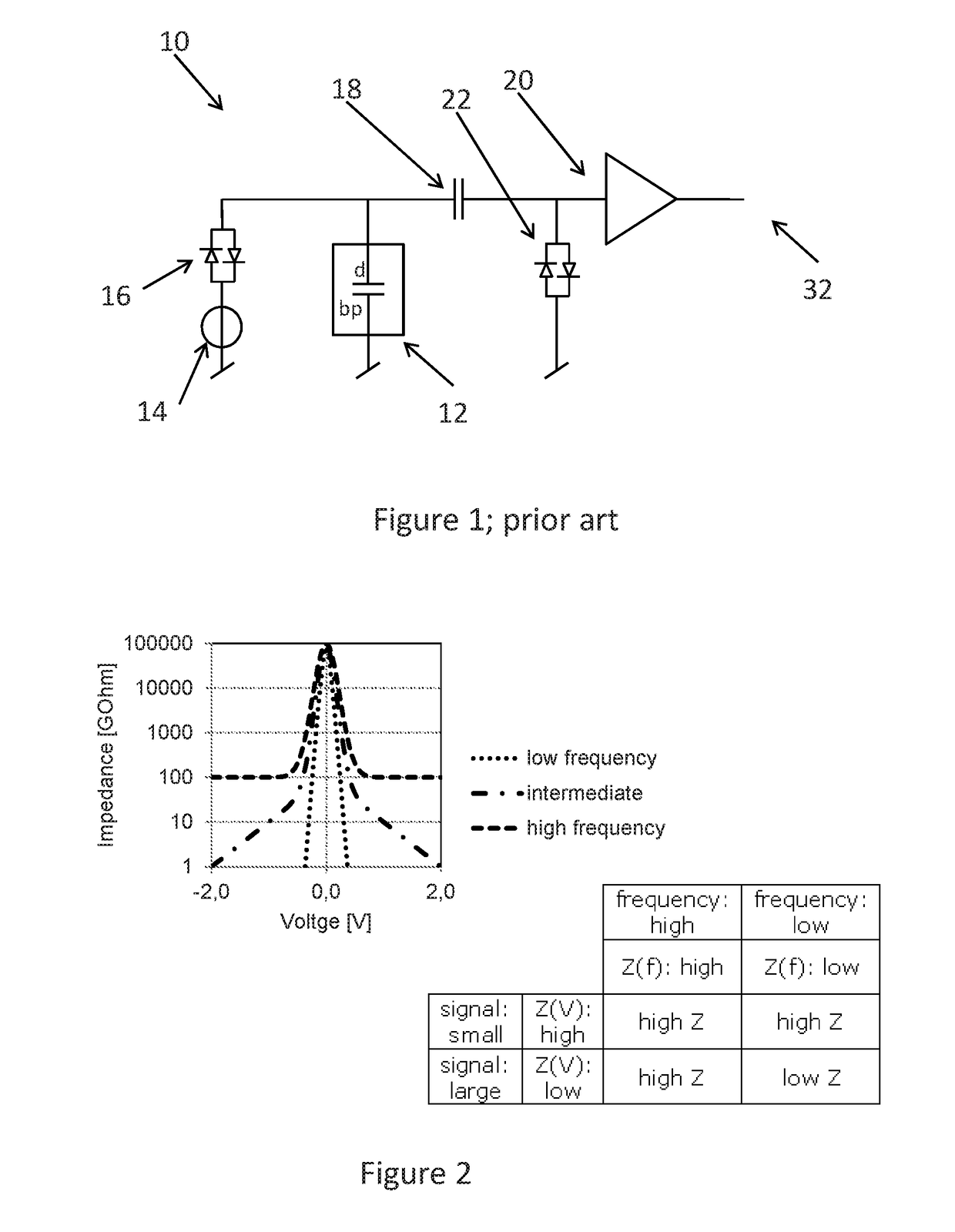
[0166]In FIG. 1, the usual system is illustrated wherein a capacitive transducer 12 has two terminals, where an upper terminal is biased by a charge pump 14. The biasing voltage is supplied via a high impedance circuit, here in the form of a pair of anti parallel diodes 16. The upper terminal, which in this embodiment is connected to the diaphragm, d, which in this embodiment is connected to an input of an amplifier 20 via a DC decoupling capacitor 18 maintaining the constant charge mode of the transducer 12. The biasing voltage may be provided to any terminal of the transducer, and any terminal may be used for outputting the signal thereof.
[0167]The lower terminal of the transducer is connected to ground. Also provided is a second high impedance circuit 22, also in the form of a pair of anti parallel diodes, preventing the output of the transducer 12 from exceeding the forward voltage of the diodes.
[0168]Ideally, the element 22 to be used for biasing the input of the amplifier to a...
PUM
 Abstract
Description
Claims
Application Information
 - R&D
- Intellectual Property
- Life Sciences
- Materials
- Tech Scout
- Unparalleled Data Quality
- Higher Quality Content
- 60% Fewer Hallucinations
Browse by: Latest US Patents, China's latest patents, Technical Efficacy Thesaurus, Application Domain, Technology Topic, Popular Technical Reports.
© 2025 PatSnap. All rights reserved.Legal|Privacy policy|Modern Slavery Act Transparency Statement|Sitemap|About US| Contact US: help@patsnap.com


