Apparatus and method for the microbiological control of fluids using electric and magnetic fields generated from alternate electrical current of low voltage and low frequency

a microbiological control and electric and magnetic field technology, applied in the direction of cleaning hollow articles, specific water treatment objectives, water/sludge/sewage treatment, etc., can solve the problems of high material corrosion rate, material destruction, and destruction of injection pipe equipment and wells, so as to prevent or reduce bio fouling and/or biofilm formation, the effect of reducing the proliferation of bacteria

Active Publication Date: 2018-05-31
SILVA DE JESUS BERNARDO ALBERTO
View PDF0 Cites 2 Cited by
  • Summary
  • Abstract
  • Description
  • Claims
  • Application Information

AI Technical Summary

Benefits of technology

[0037]The present invention comprises an apparatus and method for eliminating the proliferation of bacteria. In order to prevent or reduce bio fouling and / or biofilm formation on the inner surfaces of conductive or not conductive of electricity material pipes or equipment and / or industrial plants or process. And thus preventing the formation of dangerous gases for human being, animals and plants, such as sulfhydric acid (H2S) produced by contaminated fluids with bacterial microorganisms. The invention uses strong electric fields and magnetic fields (EMF) induced between 1 μT and 300 μT. These EMF are generated from alternating current low voltage between 0.1 V and 12 V, preferably between 0.21 V and 2.78 V, low frequency 20-100 Hz, preferably between 20 and 60 Hz and an intensity between 5 amps and 100 amps. The generation of such electric fields are automatically controlled by a computer program (software).
[0039]Each cell comprises at least one first electrical conductor wire which is introduced into the inside of the pipe through a stuffing box. Stuffing box prevents the fluid leaking. This wire runs the length of the pipe to exit by another stuffing box and connects to the outside of the pipe in a nearby end of the cell point where first cable was introduced. At least one second electric isolated wire connected with the pipe near to the end where the first electrical conductor wire came outside. The two free ends of the first and second wire connectors are connected to a low voltage and low frequency AC power source.
[0043]To each cells, is applied the voltage that generates the current which in turn form the electric and magnetic fields. Passing through the apparatus, the fluid is subjected to these strong electric and magnetic confined fields, which are permanent or pulsed, producing pores in the protective outer membranes of bacteria, allowing external fluid to enter them to lyse and in this form, the bacteria die. With the destruction of bacteria, the formation of bio-film on the inside of the pipes carrying the fluid being treated is prevented. Once bacteria die all harmful effects are prevented.

Problems solved by technology

These bacteria produce high rates of material corrosion, which eventually cause materials destruction.
In the case of oil production fields, when high concentrations of H2S are generated, destruction occurs by corrosion of injection pipe equipment and wells.
Causing often the abandonment of oil fields because the danger operation under these conditions, thus losing valuable oil reserves.
In addition to economic damage resulting from the loss of equipment and non-exploitation of oil reserves, production of H2S causes high pollution of the environment and can affect the health and even the life of living beings, whether human, animal or plants.
Most biocides wear out breaking the biofilm and when the biocide reach the bacteria, biocide do not have enough power, or the concentration required to kill bacteria is low and under these conditions the bacteria develop resistance to biocides.

Method used


Image

  • Apparatus and method for the microbiological control of fluids using electric and magnetic fields generated from alternate electrical current of low voltage and low frequency
  • Apparatus and method for the microbiological control of fluids using electric and magnetic fields generated from alternate electrical current of low voltage and low frequency
  • Apparatus and method for the microbiological control of fluids using electric and magnetic fields generated from alternate electrical current of low voltage and low frequency

Examples


example 1

of EMF in a Section of the Apparatus of the Present Application

[0112]To demonstrate the importance of the connection arrangement, in FIGS. 6A to 6E a schematic representation of the EMF performance in a section of the apparatus in the present application is made. Where Rt=pipe resistance, Rc=wire resistance. V=voltage, A→B=insulated electric conductor, C→D=metal pipe, I=current, B=magnetic field, E=electric field, =AC source, =transformer.

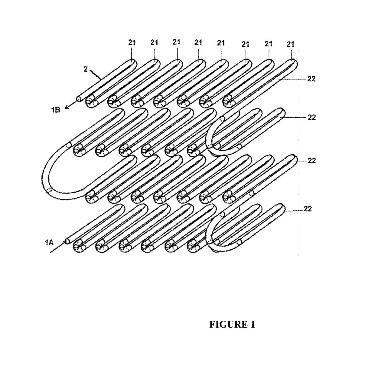
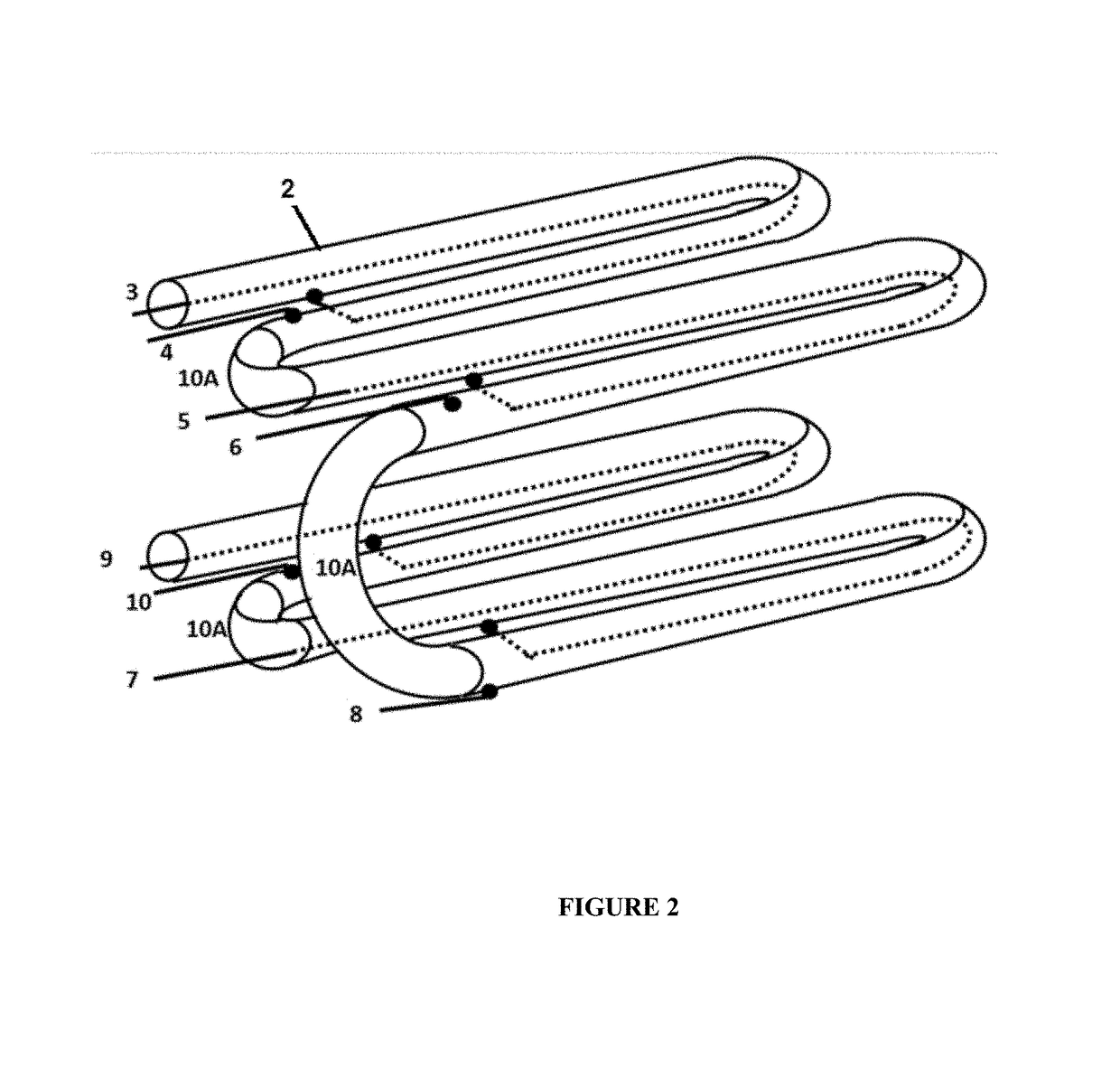
[0113]The direction and power of EMF's depend on the way the conductor cable and the pipe carrying the fluid to be treated electromagnetically to control the bacterial content are connected. FIG. 6A represents a cell (21), where the arrangement of the electrical connection apparatus of the present application is shown. Applying an AC voltage between points A and D so that the electric current flowing through the insulated electric wire (12) between points A and B through the resistance Rc (resistance of wire), then the electrical current flows thro...

example 2

ce of EMF in a Section of an Existing Apparatus in the Prior State of the Art

[0117]The closest prior state of the art has a connection between the electrically conductive cable that goes inside and the pipe equivalent to the connection shown in FIG. 7A. Therein the electric circuit is equivalent to that shown in FIG. 7B. In this arrangement the flow of the current is reversed through the pipe. The alternating electrical current enters through A, passes through the electrical conductor that goes inside the pipe to B and then electrical current enters the tube in C, and makes the journey through the pipeline to the point D. The direction of magnetic field generated by current passing through the electrical conductor wire (inside the pipe) will be the shown in FIG. 7C. The direction of the magnetic field generated within the pipe will be the shown in 7D. As it can be seen tangential force of these magnetic fields is canceled and the resultant of the magnetic fields will have the direct...

example 3

ratus and Method at the Laboratory Level

[0120]To proof this invention an apparatus and method at laboratory level was developed, it was found that due to the low resistance of the conductor and the piping (Rt=7.2 milliohms; Rc=36.65 milliohms) when the applied voltage ranged between 0.21 and 2.78 V, a high electrical current flows, in the order of 5-63 amps. This current generates electromagnetic fields (EMF) with high power between 51 μT and 104 μT, which are confined within the pipe. These EMF's induces electroporation and bioelectric phenomena that destroys the membranes of bacteria that carry the fluid to be treated.

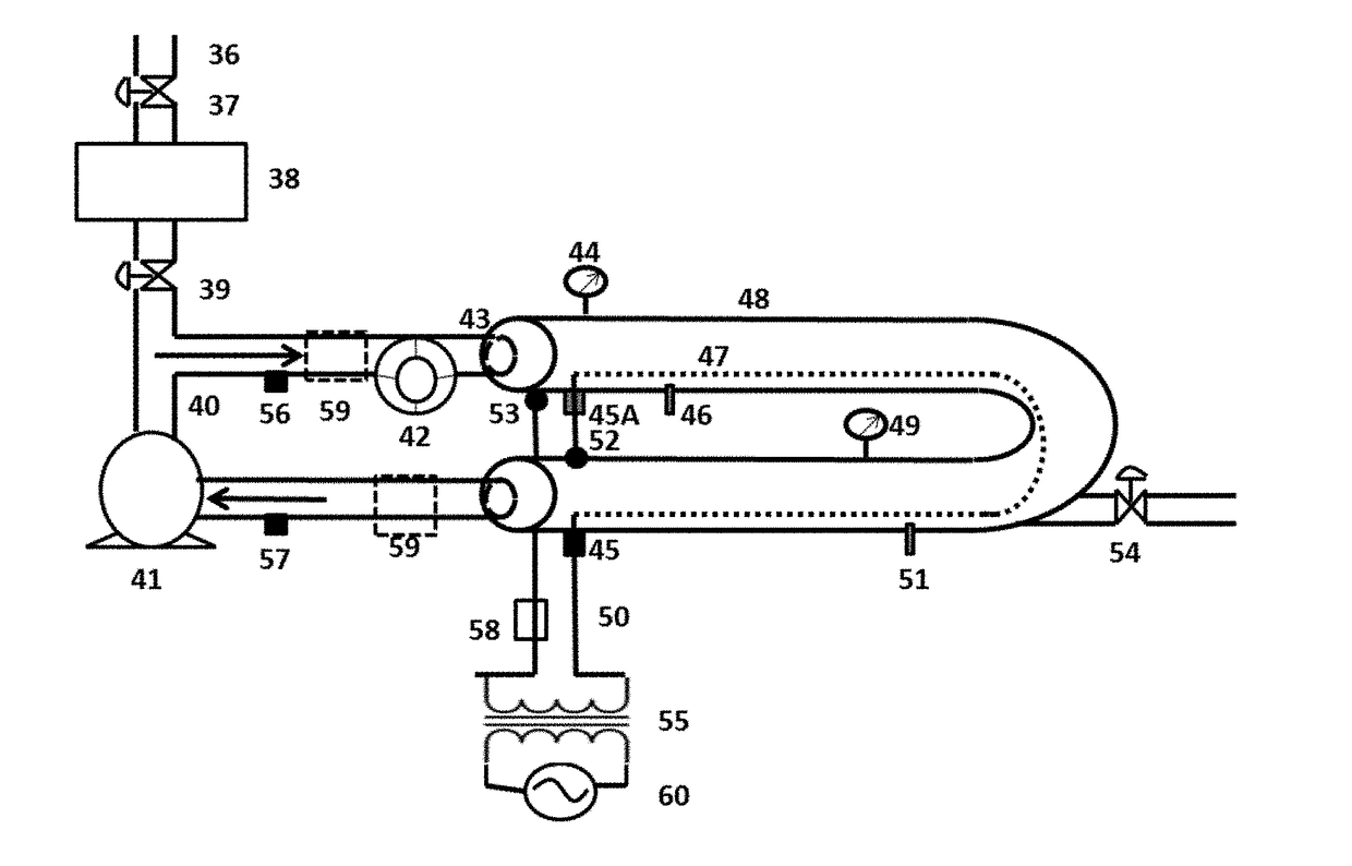
[0121]In the laboratory equipment, see FIG. 9, the microbiologically contaminated fluid enters the inlet (36) and ensures no contamination of the environment by means of valve (37). Within the tank (38) remains the contaminated fluid ready to enter the hydraulic circuit, where the EMF is generated. The valve (39) ensures that there is no mixing of the fluid being tre...


PUM

PropertyMeasurementUnit
alternating current voltageaaaaaaaaaa
frequencyaaaaaaaaaa

Abstract

The present application relates to an apparatus and method for fluids microbiological control in electrical conductive or not electrical conductive current pipes, by applying electric and magnetic fields generated from alternating electrical current of low voltage and low frequency. The apparatus is characterized by comprising a set of cells (21) of piping being electrical conductor or not, separated by electrical insulating joints (10A), but hydraulically interconnected to form sections (22) arranged or connected in series. The apparatus has an electrical arrangement that allows the direction of the magnetic field generated by the current passing through the insulated electric wire, which goes inside the pipe, be added to the direction of magnetic field generated within the pipe. The result of the sum of these magnetic and electrical fields is a tangential reinforced force. The reinforced resultant has helically—centrifuged form with direction to the inner wall of the tube (which carries lots of electrons). These electromagnetic forces push bacteria to the inner tube surface. These forces stress the membrane of these microorganisms and generating pores in the membrane, which eventually causes total lysis.

Description

CROSS-REFERENCE TO RELATED APPLICATIONS[0001]This application is the entry into national phase of International Application No. PCT / IB2016 / 054592 filed on Jul. 30, 2016, the content of which is hereby incorporated by reference in its entirety, which claims the benefit of Colombian Application No. 15-190523 filed on Aug. 14, 2015, the content of which is hereby incorporated by reference in its entirety.FIELD OF TECHNOLOGY[0002]The present invention relates to an apparatus and a method for microbiological control of industrial waters from different origins and uses, by applying electric and magnetic fields (EMF). Electro-Magnetic-Fields generates pores in the membranes of contaminating organisms, causing their breaking and thus the destruction of cells that produce biofilms on pipelines. In this invention specifically, a device that uses Alternate Current (AC) low voltage and low frequency is disclosed. And through a specific arrangement of electrical circuits generates strong electri...

Claims


Application Information

Patent Timeline
Patent Type & Authority Applications(United States)
IPC IPC(8): C02F1/48B08B9/027
CPCC02F1/484B08B9/027C02F2201/48C02F2303/04C02F2303/20
Inventor SILVA DE JESUS, BERNARDO ALBERTOSILVA RAMIREZ, MARTHA LUCIASILVA SILVA, ANDRES MAURICIOSILVA SILVA, JULIAN FELIPE
Owner SILVA DE JESUS BERNARDO ALBERTO
Why Eureka
Try Eureka