
Transparent Laminate

Active Publication Date: 2018-05-31
DEXERIALS CORP
View PDF2 Cites 20 Cited by
  • Summary
  • Abstract
  • Description
  • Claims
  • Application Information

AI Technical Summary

Benefits of technology

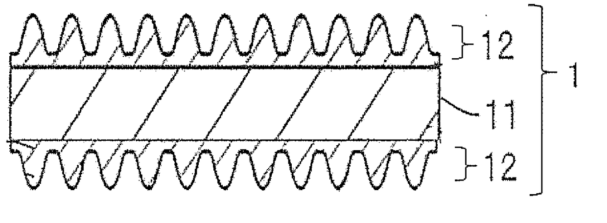
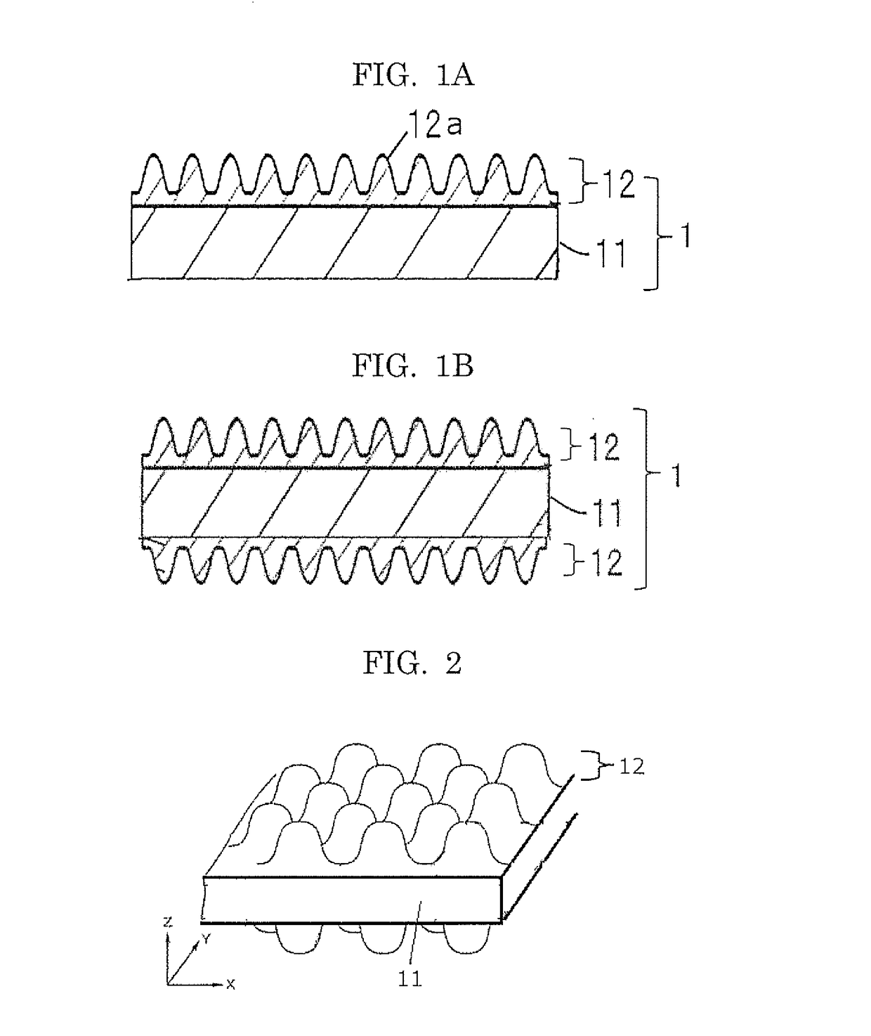
The present invention provides a transparent laminate with low reflection, good visibility, anti-fogging and wiping capability, and excellent adhesion to substrate and releasability from a master.

Problems solved by technology

However, shields having excellent visibility with low reflection and desired transparency are desired because reductions in work efficiency or fatigue of users may be caused by reductions in visibility when a transmittance is reduced due to surface reflection of the shield or external light reflection is caused.
Moreover, shields having excellent anti-fogging are desired because visibility is impaired when the shields are fogged by breath of users wearing the shields.
In the case where a shield has a surface having excellent hydrophobicity in order to obtain anti-fogging, there is a problem that a wiping capability may be impaired because the surface has excellent compatibility to aqueous pollutants.

Method used


Image

  • Transparent Laminate
  • Transparent Laminate
  • Transparent Laminate

Examples


example 1

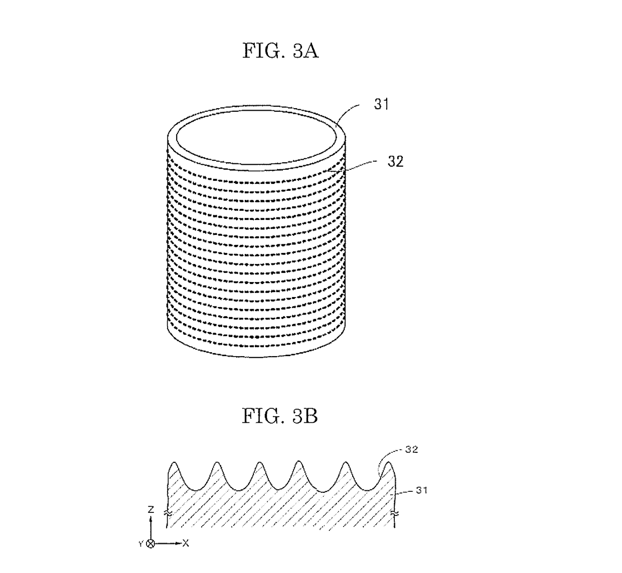
[0211]First, a glass roll master having an outer diameter of 126 mm was prepared, and a resist layer was formed on the surface of the glass roll master as follows. That is, a photoresist was diluted with a thinner to a mass ratio of 1 / 10, and the columnar surface of the glass roll master was coated with the resist diluted, by a dipping method, so that the average thickness was about 70 nm, thereby forming a resist layer. Next, the glass roll master was conveyed to the roll master exposure apparatus illustrated in FIG. 4, and the resist layer was exposed to thereby allow a latent image being continuous in a helix and forming a hexagonal lattice pattern among three adjacent rows of tracks to be patterned on the resist layer. Specifically, a region where a hexagonal lattice exposure pattern was to be formed was irradiated with laser light at 0.50 mJ / m in an image shape, to form a hexagonal lattice exposure pattern.

[0212]Next, the resist layer on the glass roll master was subjected to a...

examples 2 to 6

[0222]Each transparent laminate was obtained in the same manner as in Example 1 except that the ultraviolet curable resin composition for the structure layer in Example 1 was changed to each composition shown in Table 1-1 below.

[0223]In order to evaluate properties of each transparent laminate obtained, the same measurements and evaluations as in Example 1 were performed. The results are shown in Table 2-1.

[0224]Note that, in Table 1 (Tables 1-1 to 1-3 may be collectively referred to as Table 1), as trimethylolpropane triacrylate (TMPTA), Miramer M300 (available from Miwon) was used, and as polyethylene glycol diacrylate (the repeating number of the ethylene glycol chain=9), A-400 (available from SHIN-NAKAMURA CHEMICAL CO., LTD.) was used.


PUM

PropertyMeasurementUnit
Temperatureaaaaaaaaaa
Percent by massaaaaaaaaaa

Abstract

A transparent laminate including a transparent substrate and structure layer, wherein the structure layer contains protrusion portions, depression portions, or both on a surface thereof, and an average distance between the adjacent protrusion portions or between the adjacent depression portions is equal to or less than a visible light wavelength, the structure layer includes a polymerized product of an active energy ray curable resin composition, the resin composition includes a composition of a (meth)acryloyl group-containing polymerizable compound, the compound composition includes one or more from each of (A), (B), and (C):(A) a monofunctional (meth)acryloyl group-containing polymerizable compound;(B) alkylene glycol di(meth)acrylate; and(C) trifunctional or higher (meth)acrylate,the (A) satisfies certain conditions specifying a type and amount of a compound, and a ratio (E′150 / E′50) of storage elastic modulus E′150 of the structure layer at 150° C. to storage elastic modulus E′50 thereof at 50° C. is 0.5 or less.

Description

TECHNICAL FIELD[0001]The present invention relates to a transparent laminate.BACKGROUND ART[0002]Shields or goggles formed of transparent plastics have been conventionally used for the purpose of reducing pollutions against faces or eyes caused by splashes of coating or process powder during industrial precision operations, or for the purpose of protecting from sputtered substances.[0003]Moreover, eye shields or face shields formed of transparent plastics are used for medical applications for the purpose of preventing infections from splashes during treatments performed to patients, or for the purpose of protecting a face from sputtered substances during surgical operations.[0004]Furthermore, proposed is a shield formed of a transparent substrate that corresponds to a current diagnostic imaging device having a 3D display function and does not impair polarization optical properties for a 3D display.[0005]Several products are commercially available as a shield for protecting eyes. How...

Claims


Application Information

Patent Timeline
IPC IPC(8): C09D5/00A61F9/02A41D13/11C09D133/24C09D135/02C08F220/58C08F222/10C08J3/28G02B1/18G02B1/118
CPCC09D5/00A61F9/029A41D13/1184C09D133/24C09D135/02C08F220/58C08F222/1006C08J3/28G02B1/18G02B1/118C08J2333/24C08J2335/02C08F222/103C08F222/102A61F9/022A61F2210/0076C09D4/00C08F222/1065C08F220/281A61F9/02B32B27/16B32B27/308G02B1/111B32B2307/412B32B2307/51
Inventor OHTA, EIJIKAKINUMA, MASAYASUTAKENOUCHI, MASAKIKAWAMURA, SATOSHITANIFUJI, KIYOAKIYOSHIDA, EMINISHIMURA, KIMITAKAKAJIYA, SHUNICHIOHKAWARA, SHIGEHISAOGAWA, MAKI
Owner DEXERIALS CORP
Learn More