Laminated thin film and method for manufacturing the same

Active Publication Date: 2018-05-31
DEXERIALS CORP
1 Cites 3 Cited by

AI-Extracted Technical Summary

Problems solved by technology

However, because the hard coat layer is an organic layer and the AR laye...

Method used

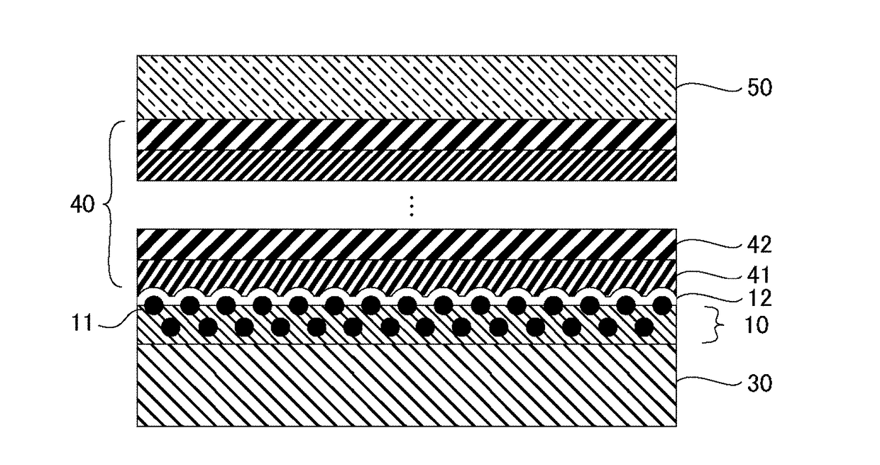
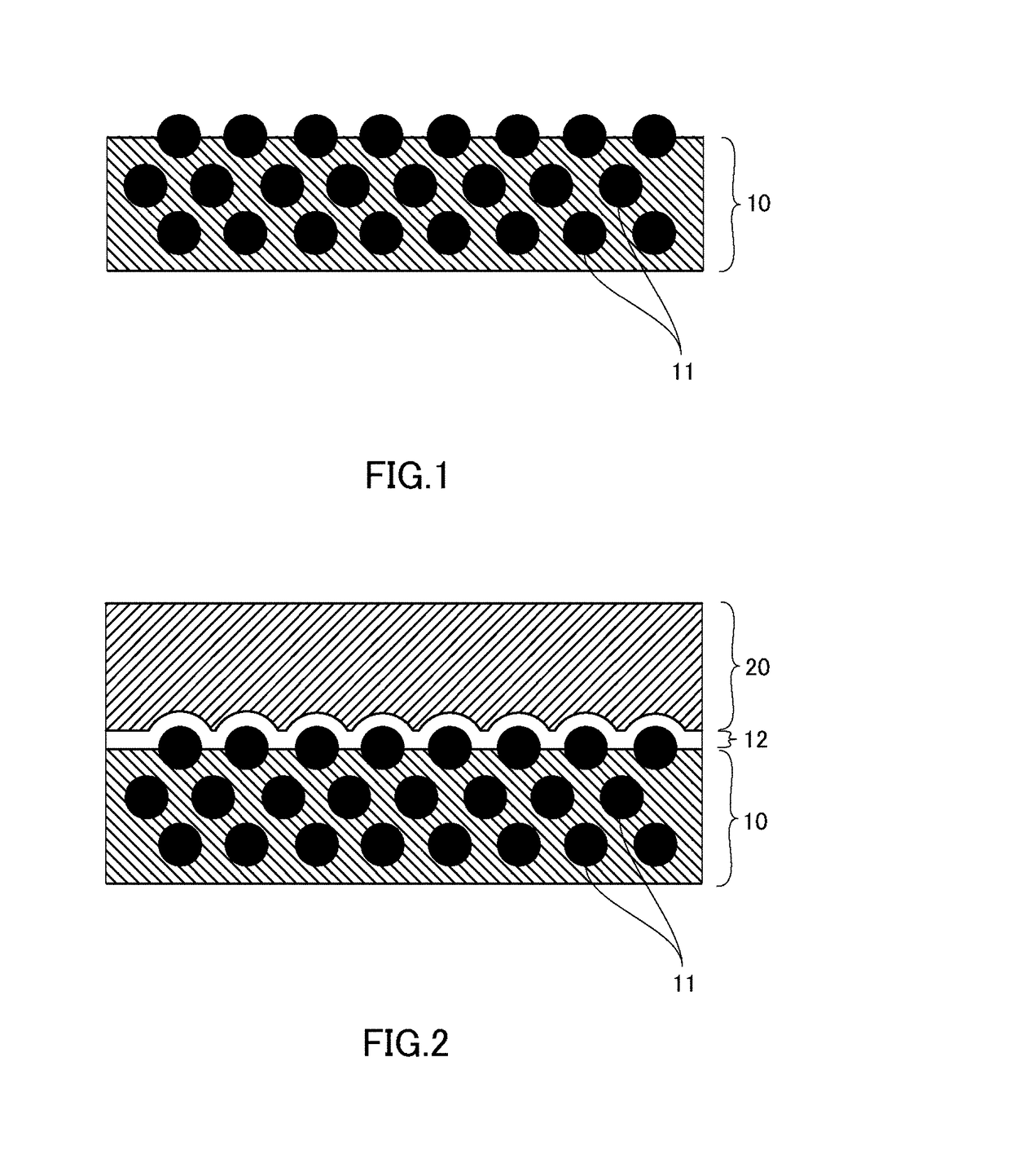
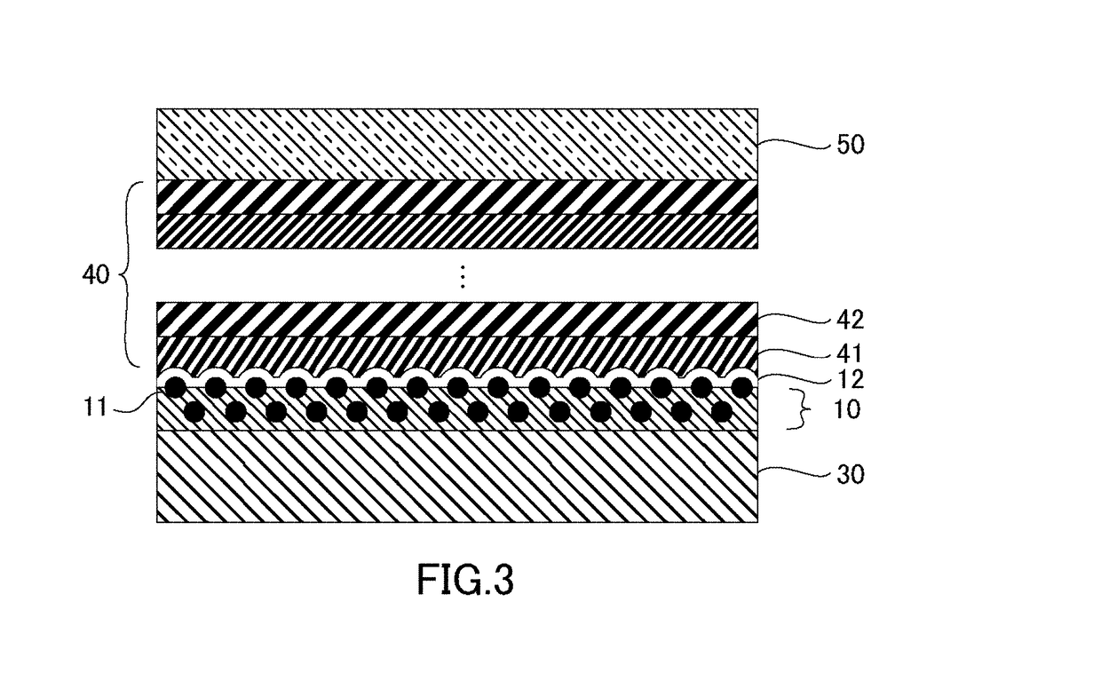
[0058]The depositing step includes depositing an adhesion layer 12 on the surface of the hard coat layer 10 on which the metal oxide particles 11 are exposed; the adhesion layer 12 is constituted by a metal or metal oxide in an oxygen-deficient state of the same metal as the metal oxide particles 11. As the method for depositing the adhesion layer 12, sputtering using a target is preferably empl...

Benefits of technology

[0009]According to the present disclosure, because the adhesion layer strongly adheres to resin of the hard coa...

Abstract

A laminated thin film having excellent adhesion between an organic and inorganic layer and method for manufacturing the same are provided. A laminated thin film is provided with a hard coat layer having a surface on which metal oxide particles are exposed; and an adhesion layer deposited on the surface of the hard coat layer on which the metal oxide particles are exposed, the adhesion layer being constituted by a metal or metal oxide in an oxygen-deficient state of the same metal as the metal oxide particles. Thereby, the adhesion layer strongly adheres to resin of the hard coat layer and adheres even more strongly to the exposed metal oxide particles, allowing excellent adhesion.

Application Domain

Technology Topic

OxideCoated surface +4

Image

  • Laminated thin film and method for manufacturing the same
  • Laminated thin film and method for manufacturing the same
  • Laminated thin film and method for manufacturing the same

Examples

  • Experimental program(23)

Example

Example 1
[0066]A photocurable resin composition was prepared which contained silica particles having a 50 nm-average particle diameter at 28 wt % with respect to total solid content of the resin composition. As represented in Table 1, the resin composition was prepared by dissolving the silica particles, acrylate, a leveling agent, and a photoinitiator in a solvent.
TABLE product manufacturer composition blend ratio acrylate CN968 Sartomer urethane acrylate oligomer 8% SR444 Sartomer pentaerythritol triacrylate 7% SR610 Sartomer polyethylene glycol (600) diacrylate 11% silica particles IPA-ST-L NISSAN 40-50 nm-diameter silica sol (solid 37% CHEMICAL content 30%, IPA solvent) leveling agent BYK377 BYK polyether-modified 0.01% polydimethylsiloxane initiator Irgacure 184 BASF initiator 1.5% solvent PGMA propylene glycol monomethyl ether 30% acetate butyl acetate 5%
[0067]Using a PET film as the matrix material, the photocurable resin composition described above was coated onto the PET film using a bar coater before photopolymerizing the resin composition to form a 5 μm-thick hard coat layer.
[0068]Next, the surface of the hard coat layer was processed with glow discharge processing at an intensity of 8,300 W*min/m2. Protrusion heights of the filler, protrusion ratios of the filler, and surface roughness Ra for the surface of the hard coat layer of Example 1 are represented in Table 2.
[0069]After glow discharge processing, using sputtering, a 10 nm-thick adhesion layer of SiOx was deposited, and an AR layer constituted by an Nb2O5 layer, an SiO2 layer, an Nb2O5, and an SiO2 layer was deposited on the adhesion layer. Furthermore, on the AR layer, a 10 nm-thick antifouling layer was formed from an alkoxysilane compound having a perfluoropolyether group, thus yielding the anti-reflective film of Example 1. This anti-reflective film had a reflectance of 0.5% or less and a water contact angle of 110 or more. Evaluation of the cross-hatch test of the anti-reflective film of Example 1 are represented in Table 2.

Example

Example 2
[0070]Except that the intensity for processing the surface of the hard coat layer using glow discharge was 4,200 W*min/m2, an anti-reflective film was prepared as in Example 1. Protrusion heights of the filler, protrusion ratios of the filler, and surface roughness Ra of the surface of the hard coat layer as well as evaluation of the cross-hatch test for the anti-reflective film of Example 2 are represented in Table 2.

Example

Example 3
[0071]Except that the intensity for processing the surface of the hard coat layer using glow discharge was 2,100 W*min/m2, an anti-reflective film was prepared as in Example 1. Protrusion heights of the filler, protrusion ratios of the filler, and surface roughness Ra for the surface of the hard coat layer as well as evaluation of the cross-hatch test for the anti-reflective film of Example 3 are represented in Table 2.

PUM

PropertyMeasurementUnit
Fraction0.5fraction
Fraction0.1fraction
Fraction0.3fraction
tensileMPa
Particle sizePa
strength10

Description & Claims & Application Information

We can also present the details of the Description, Claims and Application information to help users get a comprehensive understanding of the technical details of the patent, such as background art, summary of invention, brief description of drawings, description of embodiments, and other original content. On the other hand, users can also determine the specific scope of protection of the technology through the list of claims; as well as understand the changes in the life cycle of the technology with the presentation of the patent timeline. Login to view more.

Similar technology patents

Classification and recommendation of technical efficacy words

Why Eureka
Try Eureka