Coil component

a coil and component technology, applied in the field of coil components, can solve the problems of shortening the pitch of the coil, reducing the magnetic permeability of the magnetic layer, and needing to thin the magnetic layer arranged between the sections of the coil, so as to improve the inductance of the coil component, improve the inductance, and keep the effect small

Active Publication Date: 2018-06-14
TAIYO YUDEN KK
View PDF5 Cites 13 Cited by
  • Summary
  • Abstract
  • Description
  • Claims
  • Application Information

AI Technical Summary

Benefits of technology

[0007]As electronic devices in which coil components are installed are designed for increasingly higher performance, there is also a need for coil components offering improved characteristics such as inductance. Effective ways to improve the inductance of a coil component while keeping it small include, for example, increasing the winding density of the coil and suppressing the leakage of magnetic flux.

Problems solved by technology

However, shortening the pitch of the coil gives rise to a need to make the magnetic layers arranged between sections of the coil thinner.
However, the thinner the magnetic layers arranged between sections of the coil become, the lower the magnetic permeability of the magnetic layers becomes.
Also, the thickness of the magnetic layers formed by soft magnetic grains is naturally limited by the sizes of soft magnetic grains.
However, reducing the sizes of soft magnetic grains causes the magnetic permeability of the magnetic layers to drop.
In the case of coil components, lower magnetic permeability of the magnetic layers arranged between sections of the coil makes it difficult to achieve higher inductance, even when the winding density of the coil is increased.

Method used


Image

  • Coil component
  • Coil component
  • Coil component

Examples


first embodiment

1. First Embodiment

1.1 Overall Constitution of Coil Component 10

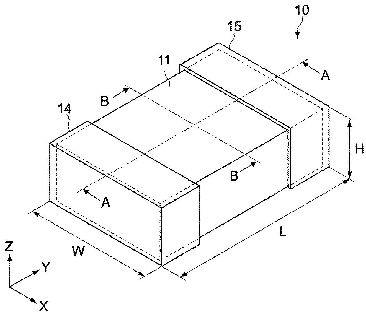
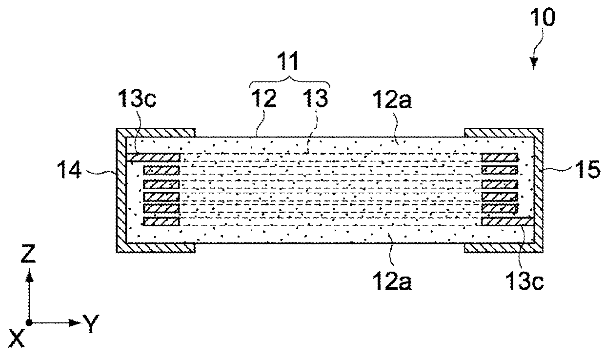
[0090]FIGS. 1 and 2 are drawings showing a coil component 10 pertaining to the first embodiment of the present invention. FIG. 1 is an oblique view of the coil component 10. FIG. 2 is a cross-sectional view of the coil component 10 along line A-A in FIG. 1. The coil component 10 is constituted as a multilayer inductor having a layer structure. The coil component 10 has a main body 11, a first external electrode 14, and a second external electrode 15.

[0091]The coil component 10 is formed as a rectangular solid shape having a width W in the X-axis direction, a length L in the Y-axis direction, and a height H in the Z-axis direction. The width W, the length L, and the height H of the coil component 10 can be determined arbitrarily. For example, the length L, the width W, and the height H of the coil component 10 may be set as 1.6 to 2 mm, 0.8 to 1.2 mm, and 0.4 to 1.0 mm, respectively.

[0092]The external electrodes 14 and 1...

example 1

1.4 Variation Example 1

[0206]FIG. 9 is a schematic view showing a part of the main body 11 of the coil component 10 pertaining to Variation Example 1 of the first embodiment. In FIG. 9, one layer of the first magnetic layers 12b, and two layers of the second magnetic layers 12c adjoining the one layer on the top and the bottom in the Z-axis direction, are extracted and shown. The coil component 10 pertaining to Variation Example 1 differs from the aforementioned embodiment only in the constitution of the first magnetic layers 12b.

[0207]Each of the first magnetic layers 12b pertaining to Variation Example 1 has one of oblate soft magnetic grain-containing layers 12b1 and two of fine grain layers 12b2. The respective fine grain layers 12b2 are arranged on the top face and the bottom face of each of the oblate soft magnetic grain-containing layers 12b1 in the Z-axis direction. It should be noted that only one of the fine grain layers 12b2 may be arranged on either the top face or the ...

example 2

1.5 Variation Example 2

[0217]FIG. 13 is a schematic view showing a micro-structure of a cross-section of the magnetic body part 12 pertaining to Variation Example 2 of the first embodiment. Each of the cover parts 12a and second magnetic layers 12c shown in FIG. 13A is constituted by the soft magnetic grains G1 and a resin F covering the soft magnetic grains G1. Each of the first magnetic layers 12b shown in FIG. 13B is constituted by soft magnetic grains G2 and G3 and the resin F covering the soft magnetic grains G2 and G3.

[0218]Unlike in the aforementioned embodiment, oxide films need not be formed on the soft magnetic grains G1, G2, and G3 pertaining to Variation Example 2. However, the soft magnetic grains G1, G2, and G3 are distributed in the resin F and thus insulated by the resin F instead of conducting with each other. Needless to say, the soft magnetic grains G1, G2, and G3 may have oxide films formed on them and may also be covered by the resin F. This means that, either w...


PUM

PropertyMeasurementUnit
thicknessaaaaaaaaaa
thicknessaaaaaaaaaa
sizeaaaaaaaaaa

Abstract

A coil component includes a magnetic body part and a coil part. The magnetic body part has first and second magnetic layers stacked together alternately in one axis direction, and cover parts covering the first and second magnetic layers from the one axis direction. The coil part has conductor patterns provided on the second magnetic layers. The magnetic body part includes: oblate soft magnetic grain-containing layers extending over the entire range of the magnetic body part in the direction perpendicular to the one axis direction, exposed in the direction perpendicular to the one axis direction, and formed by oblate soft magnetic grains whose thickness direction is oriented in the one axis direction; and spherical grain-containing layers adjoining the oblate soft magnetic grain-containing layers in the one axis direction, and formed by insulative spherical grains.

Description

BACKGROUNDField of the Invention[0001]The present invention relates to a coil component having a magnetic body part formed by soft magnetic grains.Description of the Related Art[0002]It is widely known that the magnetic bodies of coil components used at high frequencies are ferrite cores. On the other hand, Patent Literatures 1 to 3 disclose coil components that are constituted by magnetic bodies constituted by soft magnetic alloy grains. These coil components achieve higher saturation characteristics than those using ferrite cores achieve.[0003]Unlike ferrites, soft magnetic alloys have conductivity, so the coil components described in Patent Literatures 1 to 3 require constitutions that ensure insulation property of the magnetic body part. Patent Literature 1 uses a constitution whereby the soft magnetic alloy grains are coated with resin. Patent Literatures 2 and 3 use a constitution whereby oxide films are formed on the surfaces of soft magnetic alloy grains.BACKGROUND ART LITER...

Claims


Application Information

Patent Timeline
Patent Type & Authority Applications(United States)
IPC IPC(8): H01F17/00B22F1/02H01F27/255H01F27/28H01F1/147H01F1/20B22F1/08B22F1/102B22F1/16
CPCH01F17/0033B22F1/02H01F27/255H01F27/2804H01F1/14766H01F1/20H01F17/0013H01F41/0246H01F41/04H01F2027/2809H01F1/24H01F1/36H01F17/04H01F27/292H01F2017/0066H01F2017/0093H01F2017/048B22F7/02B22F2998/10B22F2999/00B22F1/16B22F1/08B22F1/102B22F3/02B22F3/1007B22F2201/03B22F2201/50
Inventor HACHIYA, MASAHIROMATSUURA, HITOSHIARAI, TAKAYUKIKURAHASHI, SHUHEIMACHIDA, HIDEOTESHIGAWARA, HIDEKAZUHONMO, NAOYA
Owner TAIYO YUDEN KK
Why Eureka
Try Eureka