
Combination Of 3D Ultrasound And Computed Tomography For Guidance In Interventional Medical Procedures

a 3d ultrasound and computed tomography technology, applied in the direction of ultrasonic/sonic/infrasonic image/data processing, angiography, application, etc., can solve the problems of vascular anatomy, difficult navigating catheter inside the vessels of patients, and inability to capture soft tissue structure of patients well

Active Publication Date: 2018-06-21
GENERAL ELECTRIC CO
View PDF4 Cites 7 Cited by
  • Summary
  • Abstract
  • Description
  • Claims
  • Application Information

AI Technical Summary

Benefits of technology

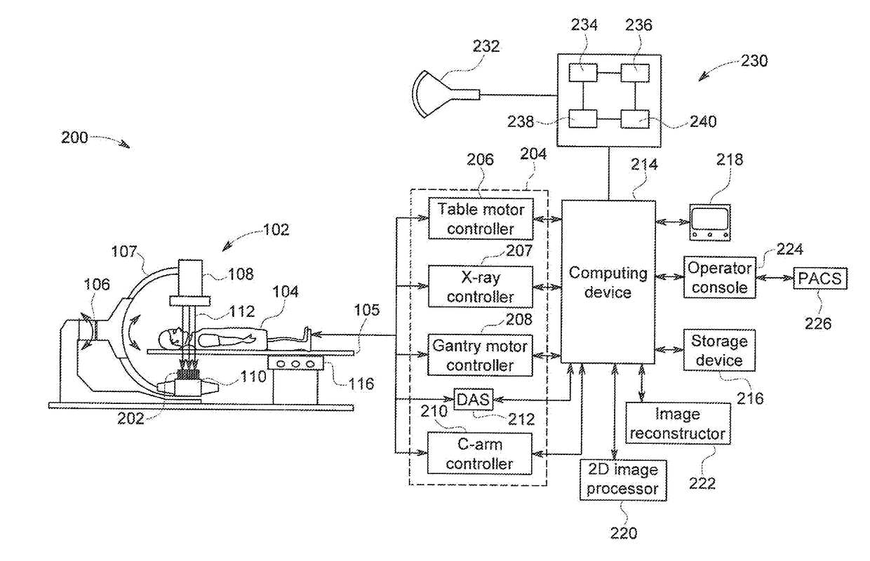
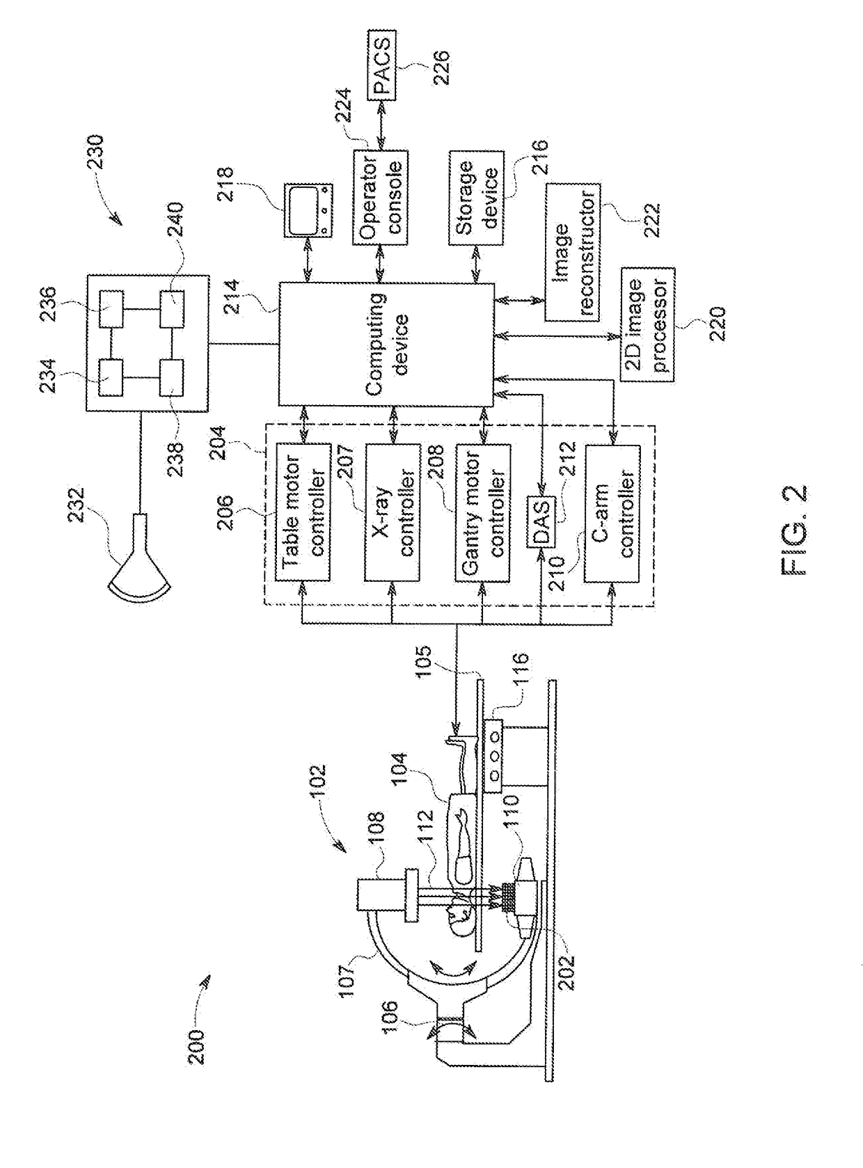
The patent describes an invention that uses an imaging system to create a fusion image of a patient's anatomy to help a medical professional insert a tool into the anatomy during a procedure. The imaging system combines real-time images with pre-operative images to create a 3D roadmap image that better matches the patient's deformed anatomy, allowing for a safer and more effective procedure. The use of ultrasound imaging also helps to correct any deformation in the vascular anatomy caused by the procedure.

Problems solved by technology

Navigating the catheter inside the vessels of a patient is challenging.
However, this imaging modality does not capture soft tissue structure of the patient well.
To achieve this task, the operator needs obviously to see the devices, which is easily achieved using fluoroscopy, but he / she also needs to understand the location of the devices versus the vascular anatomy, which is more challenging.
However the use of the contrast agent has a number of significant drawbacks.
First, the contrast agent requires a significant time to become effective and has a limited time for effectiveness within the patient before additional contrast medium is require.
Second, the contrast agent can have certain adverse effects on the paten in larger amounts, such as required for multiple X-ray sequences, including the contribution to the potential development of patient nephropathy as a result of the amount of contrast agent being injected.
Third, the increased number of X-ray sequences necessarily increases the total X-ray exposure to both patient and staff as a result of the multiple X-ray sequences being taken.
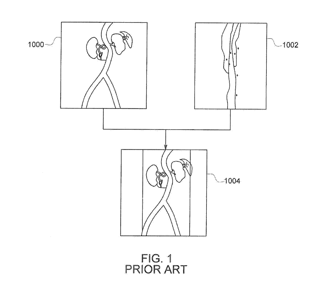
However, one significant drawback of the fusion image solution for interventional procedures, such as an EVAR procedure, is that the insertion of the interventional devices themselves during the interventional procedure deforms the anatomy of the aorta, and in particular straightens the aorta thereby moving the location of the ostia of visceral arteries from the anatomy illustrated in the pre-op CTA images.
As a consequence, after insertion of the interventional device, the anatomy depicted by the pre-op CTA image no longer matches the current patient anatomy and cannot provide an accurate roadmap for the navigation of the device through the anatomy.
First, it utilizes an injection of contrast agent to the patient, which is directly contradictory to one of the objectives of 3D roadmap / fusion image, which is to reduce the amount of contrast agent required to be injected into the patient.
Second, the final registration accuracy provided by the DSA correction may still be limited.
Since the deformation of the anatomy takes place in 3D, it is not possible, from just one 2D DSA acquired in one angulation, to find a correction that would adequately reflect deformations for the ostia of all visceral arteries.
When this is done during an interventional procedure by directly comparing the CT and ultrasound images, this requires the physician to make decision on potentially incomplete information and to do so by taking focus off of the procedure being performed, both of which are undesirable.

Method used


Image

  • Combination Of 3D Ultrasound And Computed Tomography For Guidance In Interventional Medical Procedures
  • Combination Of 3D Ultrasound And Computed Tomography For Guidance In Interventional Medical Procedures
  • Combination Of 3D Ultrasound And Computed Tomography For Guidance In Interventional Medical Procedures

Examples


Embodiment Construction

[0023]In the following detailed description, reference is made to the accompanying drawings that form a part hereof, and in which is shown by way of illustration specific embodiments, which may be practiced. These embodiments are described in sufficient detail to enable those skilled in the art to practice the embodiments, and it is to be understood that other embodiments may be utilized and that logical, mechanical, electrical and other changes may be made without departing from the scope of the embodiments. The following detailed description is, therefore, not to be taken in a limiting sense.

[0024]The following description presents embodiments of systems and methods for imaging patient anatomy in real-time during interventional and / or surgical procedures. Particularly, certain embodiments describe systems and methods for imaging processes for updating images illustrating the patient anatomy during minimally-invasive interventional procedures. The interventional procedures, for exa...


PUM


Abstract

In the present invention, an imaging system and method is provided to obtain a fusion image of a patient anatomy used as a navigational 3D roadmap to guide an interventional device into the anatomy. The fusion image fuses in real-time, fluoroscopy images taken during the interventional procedure with pre-operative CTA images, so that the operator can see the anatomy in the fluoroscopy image without having to inject contrast agent. To correct for the deformation in the anatomy from the pre-op CTA images form the insertion of interventional devices during the procedure, a 3D ultrasound image is obtained after the insertion of the devices. The 3D ultrasound images are then utilized to correct the pre-op CTA images and provide the current vascular anatomy of the patient. This updated CTA image is fused with the intra-op fluoro images to provide an accurate 3D roadmap image that matches the deformed anatomy.

Description

FIELD OF THE INVENTION[0001]The invention relates generally to tracking or delivery of medical instruments in a medical procedure, and in particular, systems and methods to track and deliver medical instruments to accommodate for deformations in patient anatomy caused during the medical procedure.BACKGROUND OF INVENTION[0002]Image-guided surgery is a developing technology that allows surgeons to perform an intervention or a surgery in a minimally invasive way while being guided by images, which may be “real” images or virtual images. For instance, in laparoscopic surgery, a small video camera is inserted through a small incision made in the patient skin. This video camera provides the operator with a “real” image of the anatomy. In other types of image-guided surgery, such as endo-vascular surgery where a lesion is treated with devices inserted through a catheter navigated into the arteries of the patient, are “image-guided” because low dose x-ray images (also called fluoroscopy ima...

Claims


Application Information

Patent Timeline
Patent Type & Authority Applications(United States)
IPC IPC(8): A61B34/20A61B6/03A61B6/00A61B8/08A61B90/00
CPCA61B34/20A61B6/032A61B6/504A61B8/0841A61B2090/378A61B8/483A61B90/37A61B2034/2065A61B2090/3762A61B6/5211A61B6/4441A61B6/487A61B6/5235A61B6/5247A61B8/5261
Inventor TROUSSET, YVES L.TARON, MAXIMEHAUION, STEPHAN
Owner GENERAL ELECTRIC CO
Learn More