Lightweight passive attenuator for spacecraft

a passive attenuator and spacecraft technology, applied in the direction of vibration dampers, cosmonautic components, cosmonautic parts, etc., can solve the problems of high load amplification, low load capacity of systems (up to 2000 kg), and inducing damage to spacecraft equipment and instruments, so as to improve shock reduction and reduce low frequency vibration

Active Publication Date: 2018-06-21
AIRBUS DEFENCE & SPACE
View PDF6 Cites 0 Cited by
  • Summary
  • Abstract
  • Description
  • Claims
  • Application Information

AI Technical Summary

Benefits of technology

[0011]The object of the present invention is to provide a light passive attenuator for spacecraft that improves the shock reduction induced by launch

Problems solved by technology

Typically these devices are activated after the stages in which the main loads occur and therefore they are not valid for the attenuation of all the events like the fairing horizontal separations.Passive systems that reduce the stiffness and the load path, like PSAD (Passive Shock Attenuation Device).
These systems, however, have low load capability (up to 2000 kg).Passive system devices that dissipate energy by the movement of a mass, like MFD (Modular Fitting Dum

Method used


Image

  • Lightweight passive attenuator for spacecraft
  • Lightweight passive attenuator for spacecraft
  • Lightweight passive attenuator for spacecraft

Examples


Embodiment Construction

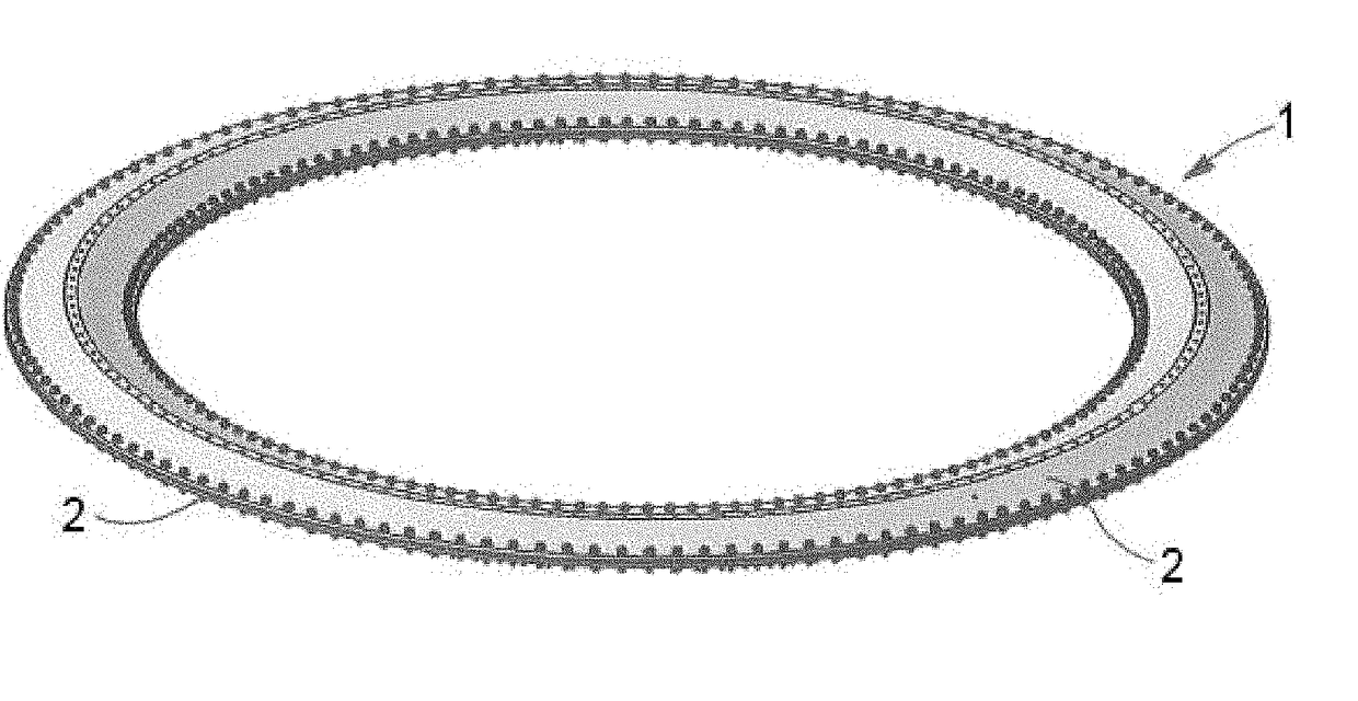
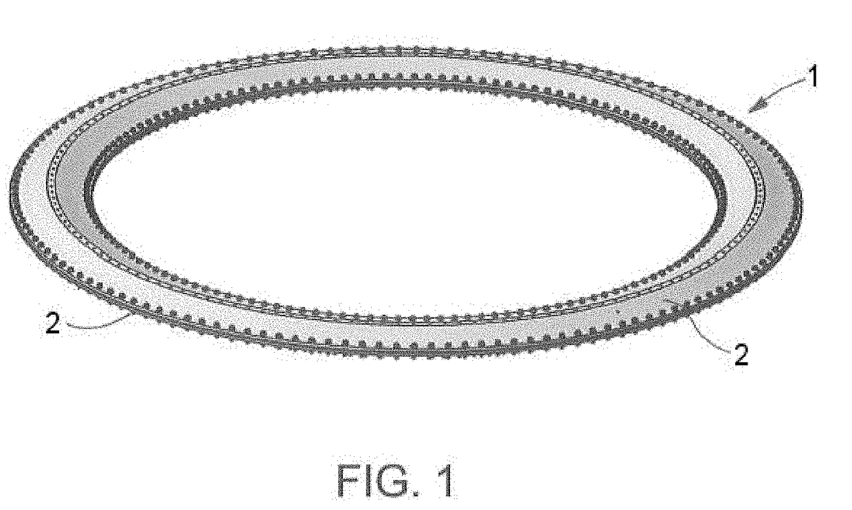
[0039]FIG. 1 shows a perspective view of the he light passive attenuator 1 for spacecraft of the invention. It is mainly formed by two omega cross-section rings 2 placed symmetrically. Between the two omega-cross rings 2 there is a gap, where a plurality of damper elements 3 are placed.

[0040]The two omega cross-section rings 2 are the main load path of the light passive attenuator 1 and are in charge of providing the stiffness.

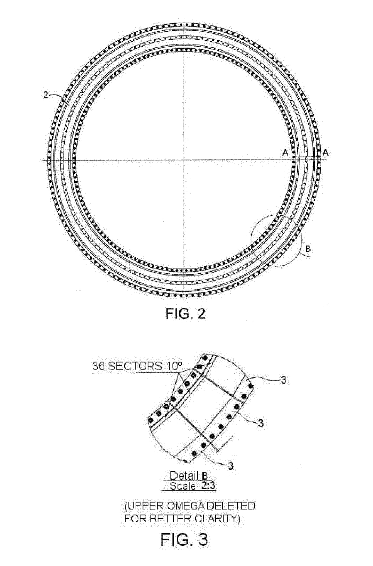
[0041]The two omega cross-section rings 2 are continuous elements which are assembled face to face. The damper elements 3 are placed in parallel with the omega cross-section rings 2, i.e., they are not in the main load path of the light passive attenuator 1. The dynamic payload isolation is obtained by a combination of elastic and damping elements (see FIGS. 8 and 9, which show the spring 9 and damper 10 elements of the light passive attenuator 1).

[0042]The omega cross-section rings 2 and the damper elements 3 are assembled at their ends by means of attachment...


PUM


Abstract

A lightweight passive attenuator (1) for spacecraft includes two omega cross-section rings (2), placed symmetrically and defining a gap therebetween, and being the main load path of the light passive attenuator (1). A plurality of damper elements (3) are placed in the gap defined between the two omega cross-section rings (2), and not in the main load path of the light passive attenuator (1), such that the omega cross-section rings (2) and the damper elements (3) are assembled at their ends by attachment elements. The omega cross-section rings (2) have a protruding central part (5) with a plurality of holes (6) for connection with adjacent structures (7, 8) of the spacecraft.

Description

FIELD OF THE INVENTION[0001]This invention refers to a light passive attenuator for spacecraft, used to reduce the shock induced by launcher pyrotechnical separations during the flight.BACKGROUND OF THE INVENTION[0002]The high level shocks generated by launcher pyrotechnic separations are a problem that has been raised for a long time, and several devices have already been developed by the applicant to reduce these shocks:[0003]Active systems that physically separate the payload from the rest of the launcher, like GSAD (Generic Shock Attenuation Device). Typically these devices are activated after the stages in which the main loads occur and therefore they are not valid for the attenuation of all the events like the fairing horizontal separations.[0004]Passive systems that reduce the stiffness and the load path, like PSAD (Passive Shock Attenuation Device). These systems, however, have low load capability (up to 2000 kg).[0005]Passive system devices that dissipate energy by the move...

Claims


Application Information

Patent Timeline
IPC IPC(8): B64G1/64F16F3/087F16F3/12
CPCB64G1/641F16F3/0876F16F3/12B64G2001/228F16F2224/0208F16F2226/04F16F1/3737B64G1/228F16F1/3732F16F1/34
Inventor LANCHO DONCEL, MIGUEL
Owner AIRBUS DEFENCE & SPACE
Why Eureka
Try Eureka