Internal combusition engine control apparatus

Inactive Publication Date: 2018-06-28
DENSO CORP
0 Cites 1 Cited by

AI-Extracted Technical Summary

Problems solved by technology

Due to this, sudden combustion may occur, thereby making it difficult to implement a clean diffusive combustion.
When the clean diffusive combustion is not implemented, there is a concern that vibration may be generated, and NOx may increase.
Radicals are unstable active substances, most of which dissipate in a short amount of time after being generated.
Therefore, when fuel is injected near the compression end of the high compression ratio engine, it becomes difficult for 0 radicals to be supplied to the fuel by ozone being supplied.
Therefore, in the conventional technology in Japanese Patent Publication No. 5906982, a p...

Benefits of technology

[0009]It is thus desired to provide an internal combustion engine control apparatus that is capable of preventing sudden combustion while ensuring ignitability in compression ignition, and actualizing a stable diffusive combustion. It is als...

Abstract

An internal combustion engine control apparatus includes a fuel injection apparatus injecting fuel into a combustion chamber a plurality of times during a single cycle, and controls an internal combustion engine that performs compression combustion. The internal combustion engine control apparatus includes an injection command unit and an injection specification determining unit. The injection command unit commands the fuel injection apparatus to perform: a main injection for a main combustion that generates torque; and a preceding injection that is performed at a stage before the main injection. The injection specification determining unit determines a penetration force of a spray produced by the preceding injection or an injection direction of the preceding injection, such that a range of reach of the spray produced by the preceding injection is closer to a nozzle hole of the fuel injection apparatus than a range of reach of a spray produced by the main injection.

Application Domain

Electrical controlInternal combustion piston engines +2

Technology Topic

Combustion chamberEngineering +5

Image

  • Internal combusition engine control apparatus
  • Internal combusition engine control apparatus
  • Internal combusition engine control apparatus

Examples

  • Experimental program(10)

Example

First Embodiment
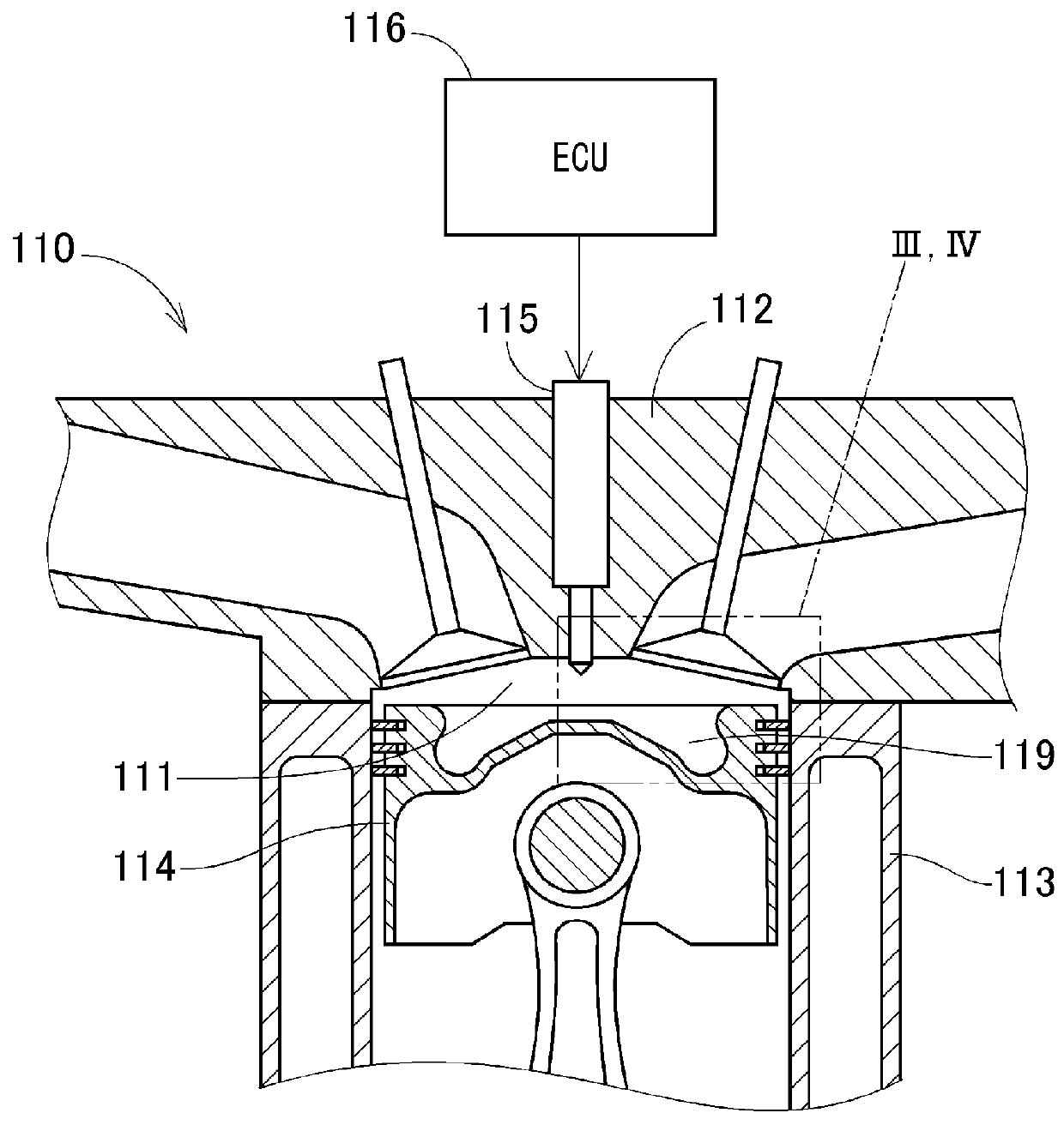
[0061]An electronic control unit (ECU) according to a first embodiment of the present disclosure serves as an internal combustion engine control apparatus. The ECU controls an internal combustion engine shown in FIG. 1.
(Internal Combustion Engine)
[0062]An internal combustion engine 110 shown in FIG. 1 uses gasoline, for example, as fuel and performs compression ignition. Compression ignition is an ignition method that takes advantage of auto-ignition of fuel that is injected into compressed, heated air inside a combustion chamber 111. The combustion that occurs at this time is diffusive combustion. In diffusive combustion, fine droplets in a spray are vaporized. Individual droplets repeatedly auto-ignite and combust. The combustion spreads to adjacent droplets, thereby resulting in a flame produced by a cluster of droplets. The injection of the fuel is performed by a direct-injection injector 115. The injector 15 directly injects the fuel into the combustion chamber 111 that is partitioned between a cylinder head 112 and a piston 114 provided inside a cylinder 113.
[0063]The injector 115 operates under the command of an ECU 116. The injector 115 injects the fuel at least twice during a single cycle. The single cycle includes an intake stroke, a compression stroke, an expansion (combustion) stroke, and an exhaust stroke. Fuel injection by the injector 115 includes a main injection and a preceding injection. The main injection is performed for a main combustion that generates torque. The preceding injection is performed at a stage before the main injection. According to the present embodiment, as shown in FIG. 2, the main injection is performed once during a period from the compression stroke to the expansion stroke. In addition, the preceding injection is performed once before the main injection, at the compression stroke. According to the first embodiment, a preceding injection timing and a main injection timing are fixed for each cycle.
[0064]The spray produced by the preceding injection undergoes a low-temperature oxidation reaction before the main injection is performed. Radicals are then generated at a timing coinciding with the main injection timing. The radicals are highly reactive intermediate products and are also referred to as cool flames. The radicals are capable of improving ignitability of fuel. The radicals are present in high concentration for only a limited period, due to chemical instability thereof. For example, the radicals that are generated from a spray that is injected at the intake stroke are likely to dissipate by the end of the compression stroke. Taking this point into consideration, the preceding injection timing according to the first embodiment is set to be at the compression stroke, such that a radical generation timing coincides with the main injection timing.
[0065]According to the first embodiment, as shown in FIGS. 3 and 4, the injector 115 has two types of nozzle holes 117 and 118. As shown in FIG. 3, the nozzle hole 118 is a hole from which the fuel is injected when the preceding injection is performed. As shown in FIG. 4, the nozzle hole 117 is a hole from which the fuel is injected when the main injection is performed. Injection directions of both nozzle holes 117 and 118 face a piston cavity 119. In addition, the nozzle hole 118 has a smaller inner diameter (hereafter, nozzle hole diameter) than the nozzle hole 117. A smaller nozzle hole diameter indicates a shorter spray reach distance x. The spray reach distance x is expressed by an expression (1), below.
[ Formula 1 ] x = ρ f ρ a d n w 0 tan θ t ( 1 )
[0066]In the expression (1), ρf denotes fuel density, pa denotes air density, do denotes nozzle hole diameter, θ denotes spreading angle of a spray, and t denotes injection time. W0 denotes speed of a spray and is proportional to a square root of injection pressure. Therefore, penetration force of the spray produced by the preceding injection (hereafter, preceding spray) is less than the penetration force of the spray produced by the main injection (hereafter, main spray). For example, JP-A-2013-119836 discloses an injector that includes two types of nozzle holes in which one nozzle hole has a smaller nozzle hole diameter than the other. Therefore, a description of a detailed configuration thereof is omitted.
(Functions of the ECU)
[0067]As shown in FIG. 5, the ECU 116 includes an information acquiring unit 121, an injection amount determining unit 122, a penetration force determining unit 123, and an injection command unit 124. The penetration force determining unit 123 configures an injection specification determining unit that determines injection specification.
[0068]The information acquiring unit 121 acquires detection values of a temperature sensor 125 and a fuel property sensor 126, and a target load of the internal combustion engine 110 that is calculated by another control unit. For example, the temperature sensor 125 is provided in the cylinder head 112 and detects a temperature of the combustion chamber 111 (hereafter, combustion chamber temperature). The temperature sensor 125 is set so as to not protrude into the combustion chamber 111 or to protrude by a miniscule amount, to prevent interference with the spray. As a result, the temperature sensor 125 can be prevented from becoming high in temperature and causing ignition. For example, the fuel property sensor 126 is provided in a fuel tank or along a fuel supply path. The fuel property sensor 126 detects a property of the fuel, such as an octane number.
[0069]The injection amount determining unit 122 first determines a total injection amount based on the target load. The total injection amount is a sum of the fuel injection amount of the main injection and the fuel injection amount of the preceding injection. Next, the injection amount determining unit 122 determines a proportion of the injection amount of the preceding injection (hereafter, preceding injection proportion) in relation to the total injection amount. Specifically, as shown in FIG. 6, the injection amount determining unit 122 increases the preceding injection proportion as the target load decreases (that is, as compression ignition becomes more difficult to perform). As shown in FIG. 7, the injection amount determining unit 122 reduces the preceding injection proportion as the target load increases (that is, as compression ignition becomes easier to perform). As a result, the amount of radicals (hereafter, radical amount) generated by the low-temperature oxidation reaction of the preceding spray becomes relatively large as shown in FIG. 6, when compression ignition is difficult. In addition, the radical amount becomes relatively small as shown in FIG. 7, when compression ignition is easy, and the main injection amount becomes relatively large.
[0070]The penetration force determining unit 123 determines the penetration force of the preceding spray such that a range of reach of the preceding spray (hereafter, preceding spray range) is closer to the nozzle hole 117 than a range of reach of the main spray (hereafter, main spray range). That is, the penetration force determining unit 123 controls a location in which the radicals are generated by the preceding spray, based on the penetration force. Specifically, during the preceding injection before the main injection for the main combustion, the penetration force determining unit 123 determines that the fuel is sprayed from the nozzle hole 18 that has a smaller nozzle hole diameter than the nozzle hole 117 used for the main injection. That is, for the preceding injection, the nozzle hole 18 that has a relatively small nozzle hole diameter is selected. For the main injection, the nozzle hole 117 that has a relatively large nozzle hole diameter is selected. As a result, a preceding spray range Rp shown in FIG. 3 is closer to the nozzle hole 117 than a main spray range Rm shown in FIG. 4.
[0071]The injection command unit 124 includes a drive circuit that drives the injector 115, and the like. The injection command unit 124 commands the injector 115 to perform the main injection and the preceding injection at the determined injection amount and the penetration force, at predetermined injection timings.
(Processes by the ECU)
[0072]The ECU 116 performs processes shown in FIG. 8.
[0073]First, at step S101, the information acquiring unit 121 acquires the combustion chamber temperature, the octane number of the fuel, and the target load of the internal combustion engine 110.
[0074]At step S102 following step S101, the injection amount determining unit 122 determines the total injection amount and the preceding injection proportion based on the target load. The preceding injection proportion is set to be greater as the target load decreases. The preceding injection proportion is set to be smaller as the target load increases.
[0075]At step S103 following step S102, the penetration force determining unit 123 determines that, during the preceding injection, the fuel is to be injected from the nozzle hole 118 that has a smaller nozzle hole diameter than the nozzle hole 117 used for the main injection, such that the preceding spray range is closer to the nozzle hole 117 than the main spray range.
[0076]At step S104 following step S103, the injection command unit 124 commands the injector 115 to perform the main injection and the preceding injection at the injection amount determined at step S102 and the penetration force determined at step S103, at the predetermined injection timings.
[0077]After step S104, the process leaves the routine in FIG. 5.
(Effects)
[0078]As described above, according to the first embodiment, the ECU 116 includes the injection command unit 124 and the penetration force determining unit 123. The injection command unit 124 commands the injector 115 to perform the main injection and the preceding injection. The penetration force determining unit 123 determines the penetration force of the preceding spray such that the preceding spray range is closer to the nozzle hole 117 of the injector 115 than the main spray range.
[0079]According to this configuration, the preceding spray can be prevented from being diffused throughout the combustion chamber 111. As shown in FIG. 4, an air-fuel mixture 129 that contains the radicals generated by the low-temperature oxidation reaction of the preceding spray is locally formed in a location near the nozzle hole 117. Therefore, a high concentration of radicals can be supplied to the main spray at the location near the nozzle hole 117. Consequently, sudden combustion can be prevented while ensuring ignitability in compression ignition. A stable diffusive combustion can be obtained. As a result, generation of vibration and increase in NOx can be suppressed. In addition, because combustion along the wall of the combustion chamber 111 is suppressed, cooling loss is reduced.
[0080]Here, the radicals are present in high concentration for only a limited period, due to the chemical instability thereof. For example, the radicals that are generated from a spray that is injected at the intake stroke are likely to dissipate by the end of the compression stroke. In addition, the spray that is injected at the intake stroke is diffused throughout the combustion chamber 111 due to the flow of intake air. In this regard, according to the first embodiment, the preceding injection is performed at the compression stroke. Therefore, the generation timing of the radicals can be set so as to coincide with the main injection timing. In addition, the radicals can be locally disposed near the nozzle hole 117.
[0081]In addition, according to the first embodiment, the nozzle hole diameter of the nozzle hole 118 used for the preceding injection is smaller than the nozzle hole diameter of the nozzle hole 117 used for the main injection. As a result, the penetration force of the preceding spray is less than the penetration force of the main spray. The preceding spray range is closer to the nozzle hole 117 of the injector 115 than the main spray range.
[0082]As a result, the radicals generated by the low-temperature oxidation reaction of the preceding spray are locally generated in a location near the nozzle hole 117.
[0083]Furthermore, according to the first embodiment, the information acquiring unit 121 is provided. The information acquiring unit 121 acquires information related to the load of the internal combustion engine 110. The injection amount determining unit 122 sets the preceding injection proportion to be greater as the load of the internal combustion engine 110 decreases. The injection amount determining unit 122 sets the preceding injection proportion to be smaller as the load of the internal combustion engine 110 increases.
[0084]As a result, the radical amount becomes relatively large under conditions in which compression ignition is difficult to perform. Ignitability is improved. In addition, the radical amount becomes relatively small under conditions in which the compression ignition is easy to perform. The main injection amount becomes relatively large. Therefore, a degree of constant-volume combustion improves and thermal efficiency increases.

Example

Second Embodiment
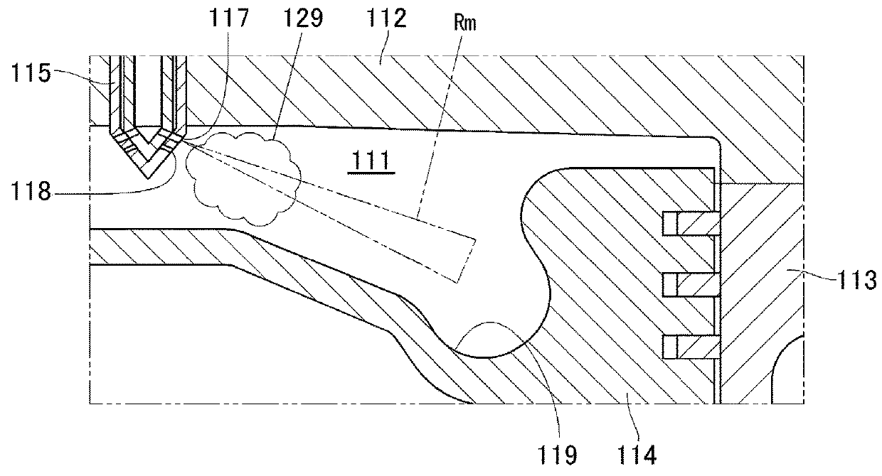
[0085]According to a second embodiment of the present disclosure, a penetration force determining unit 132 of an ECU 131 shown in FIG. 9 determines the penetration force of the preceding spray such than the preceding spray range is closer to the nozzle hole 117 of the injector 115 than the main spray range. That is, the penetration force determining unit 132 determines that, when the preceding injection before the main injection for the main combustion is performed, the fuel is injected with a smaller nozzle hole diameter and lower injection pressure than that of the main injection.
[0086]The nozzle hole diameter of the nozzle hole 118 used for the preceding injection is smaller than the nozzle hole diameter of the nozzle hole 117 used for the main injection. In addition, the injection pressure of the preceding injection is lower than the injection pressure of the main injection. The smaller injection hole diameter and the lower injection pressure indicate a shorter spray reach distance x. The spray reach distance x is expressed by the expression (1), above. In the expression (1), W0 denotes the speed of the spray and is proportional to the square root of the injection pressure. Therefore, the penetration force of the preceding spray is less than the penetration force of the main spray. The preceding spray range Rp shown in FIG. 10 is closer to the nozzle hole 117 of the injector 115 than the main spray range Rm shown in FIG. 11. For example, JP-A-2009-545701 discloses an injector in which the injection pressure is variable. Therefore, a description of a detailed configuration thereof is omitted.
[0087]Even when the injection pressure of the preceding injection is lower than the injection pressure of the main injection in this manner, the preceding spray range can be set closer to the nozzle hole 117 of the injector 115 than the main spray range. Consequently, in a manner similar to that according to the first embodiment, sudden combustion can be prevented while ensuring ignitability in compression ignition. A stable diffusive combustion can be obtained.
[0088]In addition, both the injection hole diameter and the injection pressure of the preceding injection are reduced. As a result, the preceding spray range can be set closer to the nozzle hole 117 than in cases in which only either of the injection diameter and the injection pressure is reduced.

Example

Third Embodiment
[0089]According to a third embodiment of the present disclosure, a penetration force determining unit 142 of an ECU 141 shown in FIG. 12 determines an injection direction of the preceding spray such that the preceding spray range is closer to a nozzle hole 144 of an injector 148 than the main spray range. That is, the penetration force determining unit 142 determines that, when the preceding injection before the main injection for the main combustion is performed, the fuel is injected such that the injection direction is further towards a partition wall of the combustion chamber than that for the main injection.
[0090]As shown in FIGS. 13 and 14, the injector 143 has two types of nozzle holes 117 and 144. As shown in FIG. 14, the injection direction of the nozzle hole 117 during the main injection faces the piston cavity 119. Meanwhile, as shown in FIG. 13, the injection direction of the nozzle hole 144 during the preceding injection faces an upper surface 145 of the piston 114 that is a partition wall of the combustion chamber 111. The injection direction of the preceding injection faces further towards the partition wall of the combustion chamber 111 than the injection direction of the main injection. As a result, the preceding spray range Rp shown in FIG. 13 is closer to the nozzle hole 117 of the injector 143 than the main spray range Rm shown in FIG. 14. For example, JP-A-2013-119836 discloses an injector that includes two types of nozzle holes in which the injection direction of one nozzle hole differs from the injection direction of the other. Therefore, a description of a detailed configuration thereof is omitted.
[0091]Even when the injection direction of the preceding injection faces further towards the partition wall of the combustion chamber 111 than that of the main injection, the preceding spray range can be set closer to the nozzle hole 117 of the injector 143 than the main spray range. Consequently, in a manner similar to that according to the first embodiment, sudden combustion can be prevented while ensuring ignitability in compression ignition. A stable diffusive combustion can be obtained.

PUM

no PUM

Description & Claims & Application Information

We can also present the details of the Description, Claims and Application information to help users get a comprehensive understanding of the technical details of the patent, such as background art, summary of invention, brief description of drawings, description of embodiments, and other original content. On the other hand, users can also determine the specific scope of protection of the technology through the list of claims; as well as understand the changes in the life cycle of the technology with the presentation of the patent timeline. Login to view more.

Similar technology patents

Secondary combustion chamber for household garbage flue gas

PendingCN110805910AStable combustionEasy to clean dust
Owner:安徽中泰创展环境科技有限公司

Steel slag micro-powder selecting system utilizing waste heat flue gas of steel plant

PendingCN108855941Alower fuel costsStable combustion
Owner:ZHENGZHOU WOTE ELECTRONICS TECH

Air dividing structure, burner and fuel gas cooker

ActiveCN106949473AImproves airflow speed and fluencyStable combustion
Owner:WUHU MIDEA SMART KITCHEN APPLIANCE MFG CO LTD

Control method and control device of internal combustion engine

ActiveUS20180328262A1improve ignitability
Owner:NISSAN MOTOR CO LTD +1

Preparation method of mixed fuel

InactiveCN104774669Aeasy to transportStable combustion
Owner:LANZHOU INST OF ANIMAL SCI & VETERINARY PHARMA OF CAAS

Device for fully mixing improved sanding powder and air

InactiveCN101520177AStable combustionEnergy saving
Owner:JIANGSU TAIHU BOILER

Honeycomb filter

ActiveUS20160067653A1efficiently regenerateimprove ignitability
Owner:NGK INSULATORS LTD

Classification and recommendation of technical efficacy words

  • improve ignitability

Honeycomb filter

ActiveUS20160067653A1efficiently regenerateimprove ignitability
Owner:NGK INSULATORS LTD

Control method and control device of internal combustion engine

ActiveUS20180328262A1improve ignitability
Owner:NISSAN MOTOR CO LTD +1
Why Eureka
Try Eureka