Automatic firing rate control for a heat exchanger

a technology of heat exchanger and automatic firing rate, which is applied in the direction of lighting and heating apparatus, heating types, space heating and ventilation, etc., can solve the problems of reducing the overall performance and/or life of the device, degrading the internal components of the device, etc., to prolong the life of the heat exchanger system, improve system operation, and increase performance

Active Publication Date: 2018-06-28
RHEEM MFG CO
View PDF20 Cites 10 Cited by
  • Summary
  • Abstract
  • Description
  • Claims
  • Application Information

AI Technical Summary

Benefits of technology

[0009]In an example embodiment, a target differential temperature of coolant across predetermined positions in the coolant's flow path through the heat exchanger (DT), e.g. a boiler, may be automatically controlled as a function of coolant flow through the heat exchanger and, in some embodiments, coolant specific heat. A controller may be configured to control a firing rate of a burner of the heat exchanger against a maximum allowable firing rate that is based on a predetermined relationship between DT and flow rate of coolant within the path of coolant flow in the heat exchanger. In an example embodiment, a flow sensor may be added to the heat exchanger. A flow measurement from the flow sensor may be used as an input to an intelligent algorithm, which may allow the unit to automatically adjust the maximum allowable firing rate, enabling increased performance to improve system operation and to extend the heat exchanger system's life.

Problems solved by technology

However, in more complex heat exchangers, the heat exchanger tubes may make multiple passes within the shell.
Over the life of the heat exchanger, multiple ignition sequences and cycling of the heat exchanger may cause degradation of its internal components.
In some instances, a heat exchanger may be operated under undesirable conditions, such as low flow at high firing rate, which may cause stress to the internal components of the heat exchanger, thus reducing the device's overall performance and / or life.

Method used


Image

  • Automatic firing rate control for a heat exchanger
  • Automatic firing rate control for a heat exchanger
  • Automatic firing rate control for a heat exchanger

Examples


example heat

Exchanger

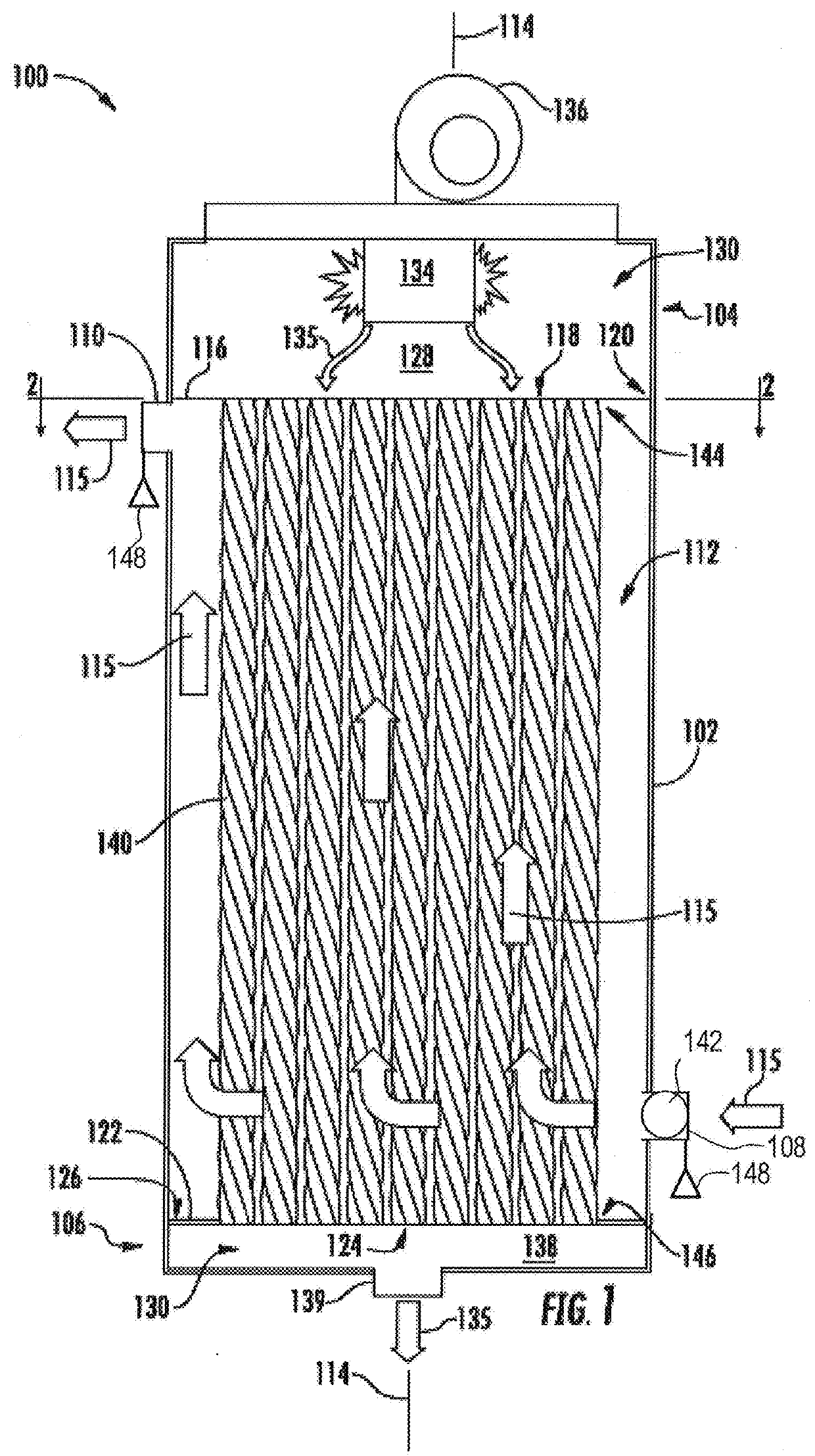
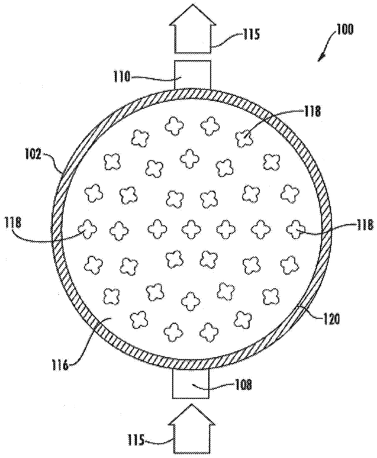
[0027]Referring now to FIGS. 1 and 2, a heat exchanger 100 may be provided, for example a fire-tube boiler, including a vertically oriented, generally cylindrical shell 102, a first end plate 116 disposed within a first end 104 of shell 102 and a second end plate 122 disposed in a second end 106 of shell 102. The heat exchanger 100 may also include a plurality of elongated heat exchanger tubes 140 disposed within shell 102, such that the elongation dimensions of the tubes 140 are all substantially parallel to the elongation dimension (e.g. a longitudinal or symmetrical center axis) 114 of heat exchanger 100 (and, more particularly, to the elongation direction or center axis of a volume of the enclosed tank defined by shell outer wall 102 and end plates or walls116 and 122). A combustion chamber 128 may be disposed in first end 104 of shell 102, and may be defined in part by first end plate 116. A burner 134 may be disposed within combustion chamber 128, and a blower 136 may...

example processing circuitry

[0075]FIG. 7, and also with reference to FIG. 1, illustrates certain elements of a controller for a heat exchanger, e.g. a boiler 100. The controller of FIG. 7 may be employed, for example, as on-board circuitry associated locally to control the heat exchanger (and may, e.g., be mounted to the heat exchanger itself), but may also be included as part of a remote user device (e.g. a remote control device that wirelessly communicates with control circuiting local to the heat exchanger), or a general purpose computer or other computer system that communicates with the heat exchanger's local circuitry via a wireless as wired local or wide area network, to thereby control the local circuitry's control of the heat exchanger's operation. Alternatively, embodiments may be employed on a combination of devices. Accordingly, some embodiments of a controller 700 may be embodied wholly at a single device or by devices in a client / server relationship. Furthermore, it should be noted that the devic...


PUM


Abstract

A heat exchanger includes a burner configured to burn a combustible gas to produce heat, a heat exchanger configured to receive the heat from the burner, a flow sensor configured to measure a flow rate of a coolant passing through the heat exchanger; and a controller comprising processing circuitry. The processing circuitry receives flow data from the flow sensor and controls a firing rate of the burner based on a predetermined relationship between a differential temperature of coolant flowing through the heat exchanger and the coolant's flow rate.

Description

CLAIM OF PRIORITY[0001]This application claims priority to U.S. Provisional Application No. 62 / 438,266, filed Dec. 22, 2016, the entire disclosure of which is incorporated by reference herein.FIELD OF THE INVENTION[0002]The present invention relates generally to heat exchangers. More specifically, embodiments of the present invention relate to controlling firing rate of a burner of the heat exchanger.BACKGROUND OF THE INVENTION[0003]Typical heat exchangers are used to transfer heat from a first fluid and a second fluid, such as from a hot combustion gas to water, etc. A typical heat exchanger includes a plurality of elongated, cylindrically-shaped heat exchanger tubes that are disposed within a shell and are substantially parallel to the shell's longitudinal center axis. In a basic heat exchanger, the heat exchanger tubes may make only one pass through the shell. However, in more complex heat exchangers, the heat exchanger tubes may make multiple passes within the shell. A combustio...

Claims


Application Information

Patent Timeline
Patent Type & Authority Applications(United States)
IPC IPC(8): F24D19/10F24D3/02
CPCF24D19/1009F24D3/02F24D19/1048F24D2200/04F24D2220/042F24D2220/044F24D2220/06F24D19/1012F24H15/35F24H15/36F24H15/421F24H15/25F24H15/238F24H15/281F24H15/215F24H15/45F24H15/31F24H15/395F24H15/219
Inventor HALLIT, RAYMONDGAMBOA, JORGE
Owner RHEEM MFG CO
Why Eureka
Try Eureka