Transducer Driver

a technology of transducer and driver, which is applied in the direction of mechanical vibration separation, power conversion system, instruments, etc., can solve the problems of affecting introducing distortion into the audio output, and degrading the implementation of control point, so as to reduce the peak current requirement and reduce the average current

Active Publication Date: 2018-06-28
ULTRAHAPTICS IP LTD
View PDF0 Cites 11 Cited by
  • Summary
  • Abstract
  • Description
  • Claims
  • Application Information

AI Technical Summary

Benefits of technology

[0017]By adding local decoupling capacitance combined with a method of constant current charging of the local decoupling capacitance, the PWM switching of the transducer can be isolated from the accumulation of the energy needed to switch the transducer minimizing the

Problems solved by technology

For the representative array of 256 transducers described above the required current can reach 4 A and realistically exceeds the peak output current of any practical consumer power supply and introduces distortion into the audio output, impacting the implementation of the control point.
Any driver circuit which connects the transducer directly to the 20V high voltage power supply has an inherent failing that there can be no power supply rejection and the power supply load transient response will drive—not couple, drive—directly into all transducers, introducing crosstalk between transducer outputs.
Since existing solutions switch large currents (problem 1) with the instantaneous current significantly varying based on numbe

Method used


Image

  • Transducer Driver
  • Transducer Driver
  • Transducer Driver

Examples


Embodiment Construction

I. Problems to be Addressed

[0024]A solution for an improved transducer driver should be designed to address at least the following problems.

[0025]Problem 1: Peak Current Required from the Power Supply is Excessive.

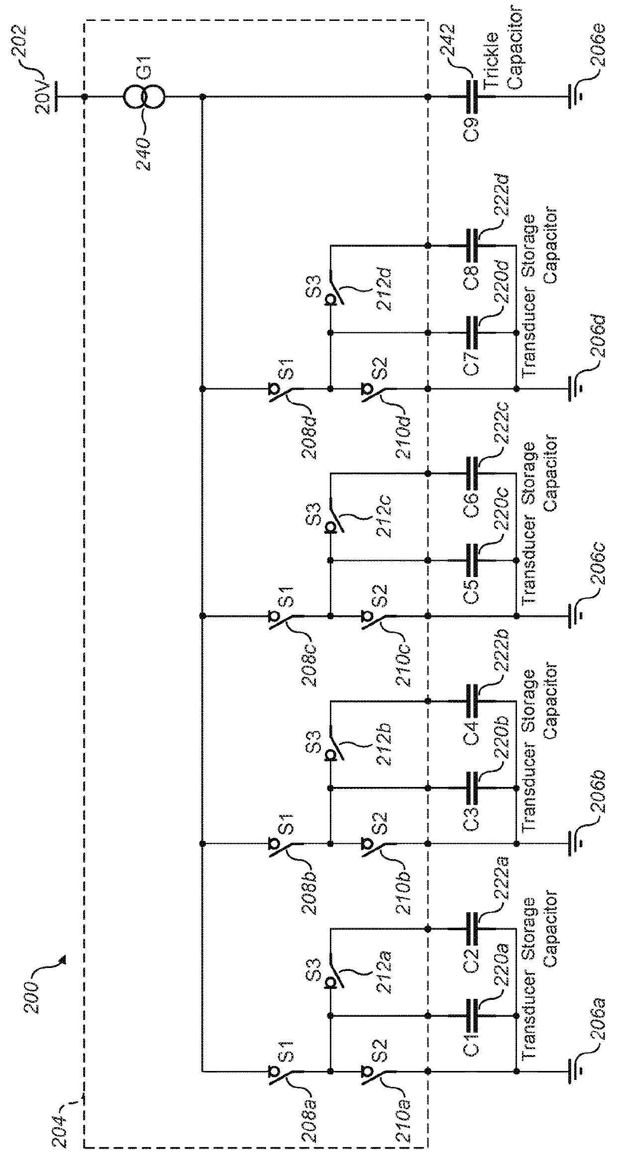
[0026]For representative array of 256 transducers described above this will be greater than 1 A.

[0027]Problem 2: Power Supply Current Varies with Number of Simultaneously Switching Transducers.

[0028]For the representative array of 256 transducers described above the required current can reach 4 A and realistically exceeds the peak output current of any practical consumer power supply and introduces distortion into the audio output, impacting the implementation of the control point.

[0029]Problem 3: Direct Drive of Transducers from the High Voltage Power Supply

[0030]Any driver circuit which connects the transducer directly to the 20V high voltage power supply has an inherent failing that there can be no power supply rejection and the power supply load transient response will...


PUM


Abstract

A circuit for driving a transducer in a mid-air haptic system includes a voltage source, a voltage sink, a current source, a trickle capacitor, a storage capacitor, a haptic system transducer, a first switch, a second switch, and a third switch. Using these components, a portion of the charge required for switching a transducer is sourced from the decoupling capacitance. When the switching completes, additional charge is transferred immediately from the power supply back into the decoupling capacitance. This acts to lower the peak current by fully utilizing 100% of a switching waveform for transfer of charge from the power supply to capacitors local to the transducer.

Description

RELATED APPLICATION[0001]This application claims the benefit of the following U.S. Provisional patent application, which is incorporated by reference in its entirety:[0002]1) Ser. No. 62 / 433,785, filed on Dec. 23, 2016.FIELD OF THE DISCLOSURE[0003]The present disclosure relates generally to improved driving techniques for acoustic transducers in mid-air haptic-based systems.BACKGROUND[0004]A continuous distribution of sound energy, referred to as an “acoustic field”, may be used for a range of applications including parametric audio and the levitation of objects.[0005]By defining one or more control points in space, the acoustic field can be controlled. Each point may be assigned a value equating to a desired amplitude at the control point. An acoustic field exhibiting the desired amplitude at the control points is created by actuating the set of transducers as a phased array. Focusing the energy in the desired control point location implies the transducers are excited at different ...

Claims


Application Information

Patent Timeline
IPC IPC(8): G10K11/34G06F3/043H02M1/096H02M1/16H01G4/002
CPCG10K11/346G06F3/0436H02M1/096H02M1/16H01G4/002B06B1/0207
Inventor TESTER, DAVID PHILIPLONG, BENJAIMIN JOHN OLIVER
Owner ULTRAHAPTICS IP LTD
Why Eureka
Try Eureka