
The energy tower of multi-energy-form output for stepwise recovering waste heat of a gas engine

a gas engine and energy tower technology, applied in steam engine plants, machines/engines, mechanical equipment, etc., can solve the problems of single waste heat recovery method not fully using the waste heat of gas engine, waste heat recovery method can only be efficiently recycled, etc., to improve the comprehensive energy utilization efficiency of the system, and different quality and functions

Active Publication Date: 2018-07-05
TIANJIN UNIV
View PDF0 Cites 6 Cited by
  • Summary
  • Abstract
  • Description
  • Claims
  • Application Information

AI Technical Summary

Benefits of technology

The present waste heat recycling system uses multiple methods to recover and utilize waste heat from a gas engine. By combining cooling, heating, and power supplying methods, the system provides energy with different quality and functions to buildings. This system maximizes the recycling of waste heat energy from the gas engine, resulting in improved energy utilization efficiency and significant energy savings and emissions reduction.

Problems solved by technology

However, any existing waste heat recovering method can only efficiently recycle the heat within a certain energy quality, therefore, a single waste heat recovering method may not make full use of the waste heat of the gas engine.

Method used


Image

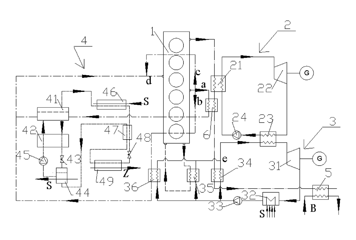
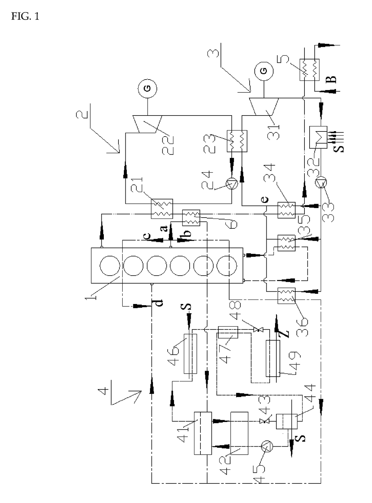
  • The energy tower of multi-energy-form output for stepwise recovering waste heat of a gas engine
  • The energy tower of multi-energy-form output for stepwise recovering waste heat of a gas engine

Examples


embodiment

[0040]The parameters of the gas engine and the waste heat source thereof in the embodiment are shown in table 1.

TABLE 1The parameters of the gas engine and the waste heat source thereof (under rated operating condition)ParameterValueRated power of gas engine1100 kWTemperature of exhausted gas540° C.Volume flow of inlet gas (under 1.16 m3 / sstandard condition)Volume flow of fuel gas (under0.0784 m3 / sstandard condition)Flow of jacket water 8.33 kg / sOutlet temperature of jacket 85° C.waterInlet temperature of jacket water 75° C.Air temperature after pressurized130° C.by the turbocharger

[0041]As the first stage for recovering the waste heat of the exhausted gas, the steam Rankine cycle system consists of the waste heat boiler, the back-pressure steam turbine, the condenser and the pump which are connected successively. In the first recovering stage, the exhaust after the turbocharger enters the waste heat boiler for heating the gas into a superheated steam under the pressure of 1.6 MPa; ...


PUM


Abstract

A multi-energy-form output energy tower for stepwise recovering waste heat of a gas engine, comprising an internal combustion engine (1), wherein the present invention also comprises a steam Rankine cycle system (2) which is capable of heat exchanging with the high temperature exhaust exhausted from the IC engine (1) to make the steam turbine (22) do expansion work. An organic Rankine cycle system which is respectively heat exchanged with high temperature exhaust, jacket water and charge air which are exhausted from the IC engine (1), and with condensation heat in the steam Rankine cycle system (2) to do expansion work; a lithium bromide refrigerator (4) which uses jacket waterpart of jacket water discharged from the IC engine (1) as a heat source of the absorption cooling system for heat exchange; and a hot water heat exchanger (5) connected with a high temperature exhaust of the IC engine (1) for heating domestic water. The energy tower of the present invention adopts multiple waste heat recovering methods and combines cooling, heating and power supplying methods, which improves comprehensive energy utilization efficiency of the system and achieves the effects of energy saving and emission reduction.

Description

FIELD OF THE INVENTION[0001]The present invention relates to an energy tower for utilizing the waste heat of an internal combustion engine, especially relates to a multi-energy-form output energy tower for stepwise recovering waste heat of a gas engine.BACKGROUND OF THE INVENTION[0002]With the scarcity of worldwide petroleum resources, internal combustion engines fueled by conventional and unconventional natural gas (short for gas engine) are being used increasingly because of their characteristics of cleanness, high efficiency, low pollution and huge potential of gas resources. In particular, a gas combustion engine for large-scale power generation together with its waste heat recovering system often takes as a set of independent system for supplying energy to the buildings. Many developed countries pay attention to this system and called it as “second generation energy system”, which is widely used in the field of energy supply for buildings. The gas engine has various waste heat ...

Claims


Application Information

Patent Timeline
IPC IPC(8): F01K27/02F02G5/04F01D15/10F01K23/18F01K25/14
CPCF01K27/02F02G5/04F01D15/10F01K23/18F01K25/14F01N2240/02F02G2260/00F01K23/00F01K25/08F01K27/00F05D2220/62F01N2240/22F01K7/38F01K23/065Y02T10/12
Inventor SHU, GEQUNWANG, XUANTIAN, HUACHE, JIAQIANGLIU, PENG
Owner TIANJIN UNIV
Learn More