System for Preventing Transformer Saturation

a technology for transformers and cores, applied in power conversion systems, circuit arrangements, ac-ac conversion, etc., can solve the problems of more abrupt saturation of the core, shortened air-to-steel ratio, and high-flux density alloys that tend to saturate abruptly

Active Publication Date: 2018-07-05
DENT ORRIS
View PDF0 Cites 3 Cited by
  • Summary
  • Abstract
  • Description
  • Claims
  • Application Information

AI Technical Summary

Benefits of technology

[0030]During each half-cycle sensor testing the PWM gating function is turned off, for example, for approximately 10% of the half-cycle duration (about 1-2 milliseconds in a 50 or 60 cycle system) after the transformer excitation voltage changes polarity. This Hold-Off interval period, during which the flux level is likely not yet affected by the reverse in primary voltage polarity, is believed to contribute to the transformer efficiently recovering from near saturation, and is desirable to prevent false triggering of saturation signals after these polarity change points. A false saturation signal at the beginning of a half-cycle would interrupt the PWM voltage for the remainder of the half-cycle, and that would not allow the transformer flux to re-center.

Problems solved by technology

However, the reduction in the ratio of air to steel leads to more abrupt saturation of the core.
Such high flux density alloys do tend to saturate abruptly at their design flux limit however, and at saturation the magnetic field in the transformer core no longer increases in direct proportion to the current in the transformer primary winding.
In fact this rise in primary current has historically been used as a 2nd order, or indirect, indicator of core saturation, but it is difficult and / or impossible to separate this indication from load related over current events due to the non-linearity of transformers.
However, line loading is almost never constant and the Volt-Second integral can be perturbed for various periods of time by a multitude of causes, sometimes to the point of causing long term transformer saturation with consequent equipment overheating and outages due to circuit breakers or fuses opening, any or all of which can result in taking equipment off line.
Also the pulsed currents caused by the saturation can disturb sensitive equipment that shares the same utility line by degrading the line voltage regulation.
In addition, it is not just long-term AC waveform asymmetry that is a problem; it is also a problem at shorter time scales.
Saturation is detrimental to equipment life and good supply voltage regulation.
However, algorithmic means are only good if the model is detailed, precise and accurate, and such means require a rather long history of the conditions in which the transformer is operated before the algorithm becomes reliable.
In other words, the algorithm is nearly useless when the transformer is first switched on.
Crafting a good model is also a difficult task, a task that must be repeated for every transformer to which the model is to be applied.
Hall-effect devices have a relatively small signal to noise ratio, a limited temperature range, and a tendency to drift.
Permeability measuring circuits and secondary core structure can be complicated, slow to respond relative to the flux change in the main core and often require individual calibration because of difficulty in precisely repeating the mechanical placement of the sensing element.

Method used


Image

  • System for Preventing Transformer Saturation
  • System for Preventing Transformer Saturation
  • System for Preventing Transformer Saturation

Examples


Embodiment Construction

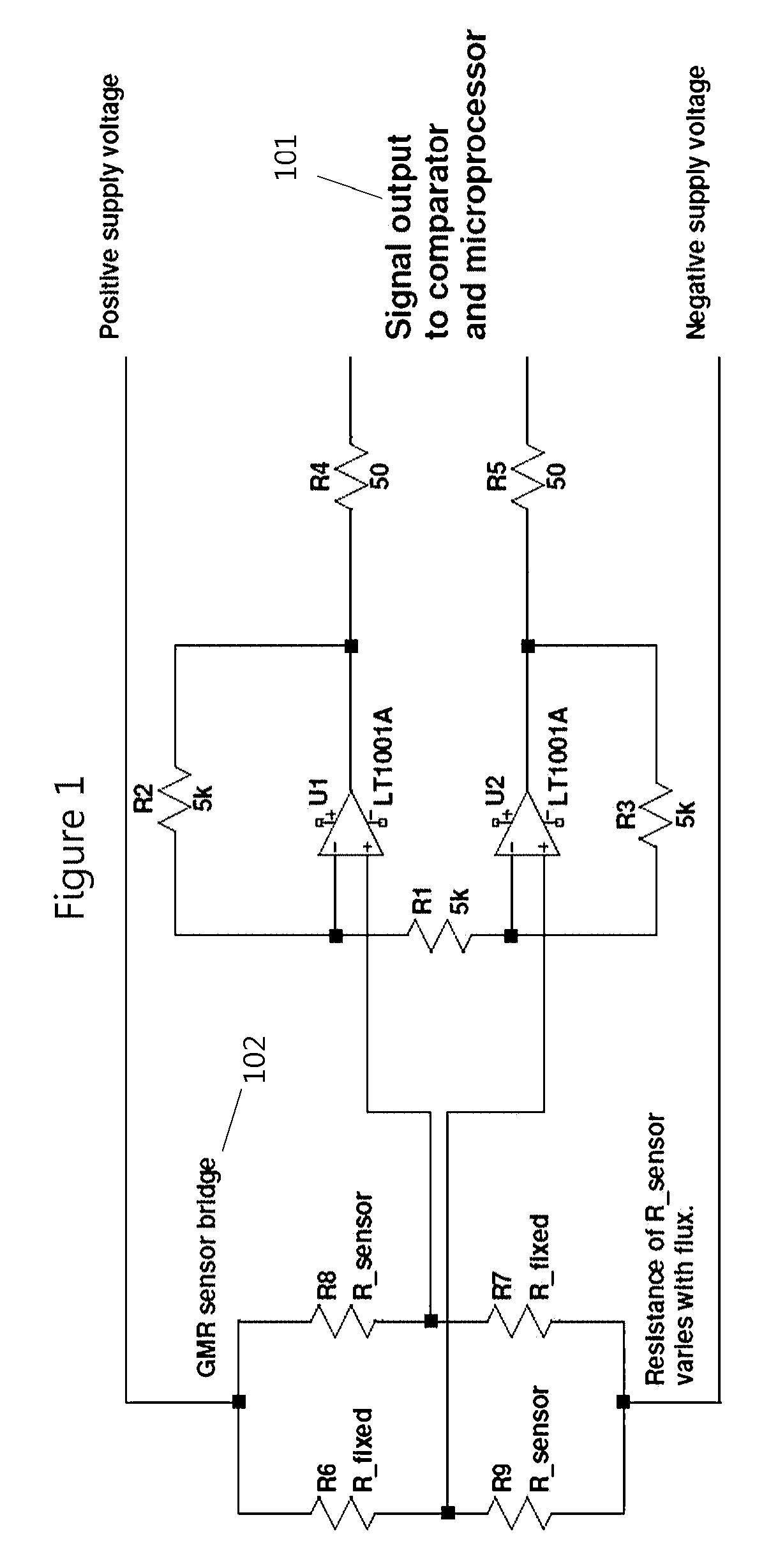
[0058]A circuit for use with bridge-configured GMR sensors is illustrated in FIG. 1. GMR sensing bridge 102 has signal output 101 to the microprocessor.

[0059]The flux sensor also enables the flux in power transformers to stay centered in the presence of any DC offset originating in the AC line. Such a circuit is further illustrated in FIGS. 3 and 5.

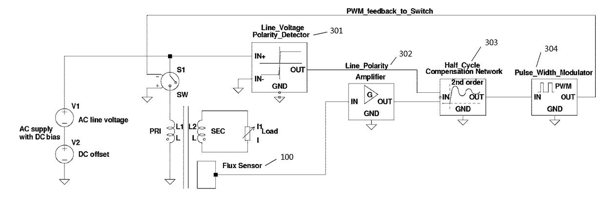
[0060]FIG. 3 is a diagram of a transformer flux centering control system that uses modulation of the AC voltage applied to the transformer primary. The Switch ON:OFF time is modulated as a function of supply line polarity and transformer flux level on a half-cycle-by-half-cycle time basis, employing conventional line voltage polarity detector 301, amplifier 302, half-cycle compensation 303, PWM 304 and novel flux sensor 100, as discussed above.

[0061]FIG. 5 provides the same function utilizing a series injection topology. The control voltage is increased or reduced each half-cycle so that the power transformer Volt-Second interval is alter...


PUM


Abstract

A system for preventing magnetic saturation in a transformer cores. A magnetic flux sensor is disposed within a bore in the core in a bore drilled or let into the material of a toroidal transformer core. The sensor transmits a sensor output that is continuously received by a microprocessor that is programed to process the sensor output and to also continuously compare in real time the sensor output with a stored selectable maximum flux sensor output value. Responsive to the comparison of real-time sensor output value to the stored maximum value, the microprocessor either allows, during each driving voltage half-cycle, the driving voltage to continue unabated while the sensor output remains below the selectable maximum value, or triggers a gate to modify the driving voltage for the remainder of the half-cycle when the selectable maximum value is reached.

Description

CROSS REFERENCE TO RELATED APPLICATIONS[0001]This application claims priority to U.S. Provisional Patent application 62 / 441329 filed Dec. 31, 2016 which is hereby incorporated by this reference as if fully set forth herein.TECHNICAL FIELD[0002]This disclosure relates to controlling magnetic flux density in a volume by modulation of the electromotive force affecting that volume proportionate to the measured magnetic flux density within the volume; more particularly it relates to transformer core saturation and methods of limiting or preventing such saturation; more particularly, it relates to feedback systems employing direct magnetic flux sensors.BACKGROUND[0003]AC line voltage regulators maintain a constant output voltage (within limits) while the line voltage input to them changes. One popular class of electronic voltage regulators utilize a series injection transformer, the secondary of which is connected in series between the input voltage terminal and the output voltage termina...

Claims


Application Information

Patent Timeline
Patent Type & Authority Applications(United States)
IPC IPC(8): H02P13/00H02H9/02
CPCH02P13/00H02H9/02H02H1/0007
Inventor DENT, ORRIS
Owner DENT ORRIS
Why Eureka
Try Eureka