Check patentability & draft patents in minutes with Patsnap Eureka AI!

System and method for in-situ measurement of viscoelastic material properties using continuous-wave ultrasound

Active Publication Date: 2018-07-26
UNIVERSITY OF MISSOURI
View PDF33 Cites 0 Cited by
  • Summary
  • Abstract
  • Description
  • Claims
  • Application Information

AI Technical Summary

Benefits of technology

The present invention is about a system and method to measure the viscoelastic properties of a material using ultrasound. The system includes an emitter transducer and an observer transducer that are positioned within the material. These transducers can be supported by different types of hardware configurations, such as a reservoir, a fixture, a rail, a conduit, or a vessel. The transducers are preferably spherically focused to minimize wave spreading loss. The technical effect of this invention is to provide a non-destructive and non-invasive way to measure the viscoelastic properties of materials in real-time, which can be useful in various fields such as materials science, biomedical research, and industrial applications.

Problems solved by technology

However, experimental measurements made with ultrasound pulses or other broad-band excitations are prone to errors because typical viscoelastic materials do not have a flat frequency response to mechanical vibrations.
As a result, viscoelastic property evaluations that rely on the use of multi-frequency excitations, such as those used with time-of-flight and phase difference techniques, often suffer from a low signal-to-noise ratio (SNR).
However, the use of continuous-wave excitations in ultrasound-based measurements has not been well developed in comparison to time-of-flight and phase difference techniques.
These techniques cannot be used in conjunction with automated processes and, in particular, the lack of a technique to measure viscosity in-situ has been a primary obstacle to optimization and automation of many processes.

Method used


Image

  • System and method for in-situ measurement of viscoelastic material properties using continuous-wave ultrasound
  • System and method for in-situ measurement of viscoelastic material properties using continuous-wave ultrasound
  • System and method for in-situ measurement of viscoelastic material properties using continuous-wave ultrasound

Examples


Embodiment Construction

[0028]The present invention is directed to a system and method for measurement of the viscoelastic properties of a material using continuous-wave ultrasound. While the invention will be described in detail below with reference to various exemplary embodiments, it should be understood that the invention is not limited to the specific configurations or methodologies of these embodiments. In addition, although the exemplary embodiments are described as embodying several different inventive features, one skilled in the art will appreciate that any one of these features could be implemented without the others in accordance with the present invention.

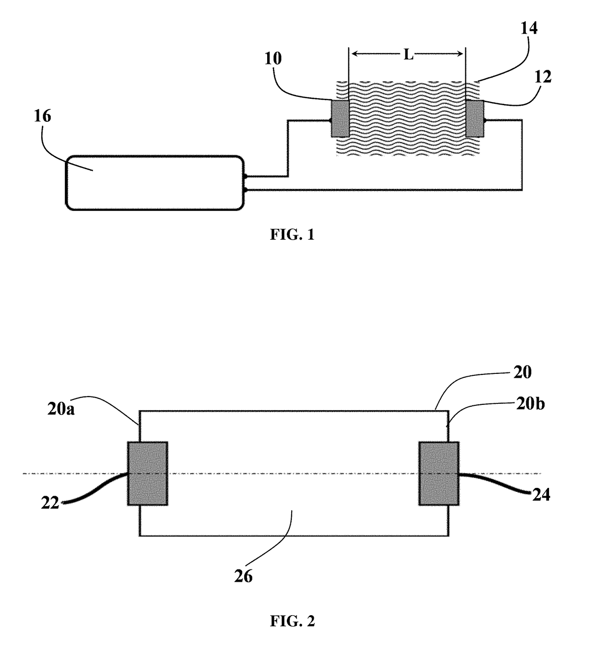
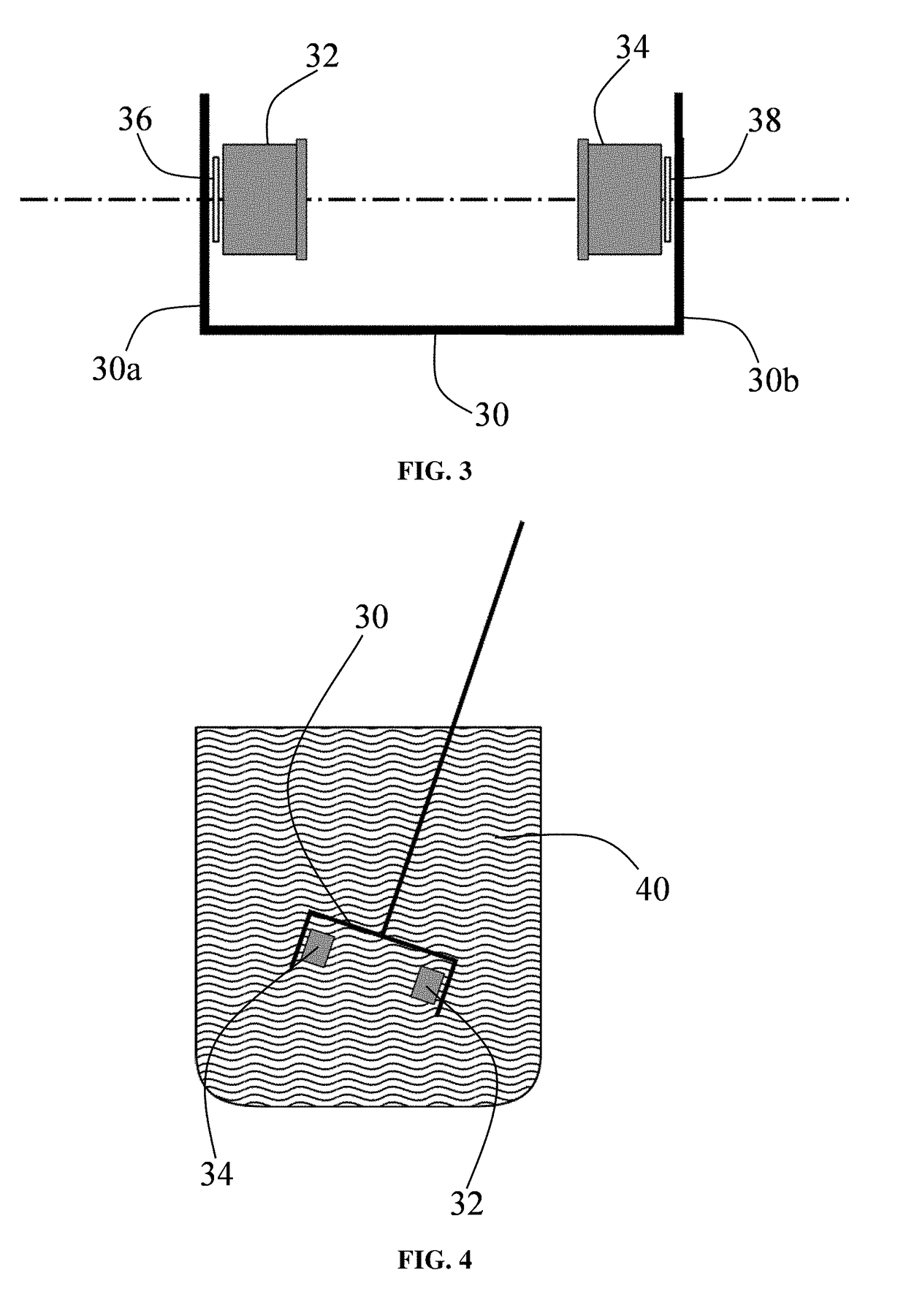
[0029]In general terms, the present invention is directed to a continuous-wave ultrasound methodology for measuring the viscoelastic properties of a material in-situ and includes the following steps: (1) provide an emitter-observer transducer pair separated by a material under measurement; (2) apply an excitation signal comprising a continuou...


PUM


Abstract

A system and method for measuring one or more viscoelastic properties of a material under measurement is disclosed. The system includes an emitter-observer transducer pair separated by the material. A signal processing assembly is operable to (i) apply a plurality of excitation signals to the emitter transducer, wherein each of the excitation signals comprises a continuous-wave sinusoidal waveform, (ii) record a plurality of output signals at the observer transducer, wherein each of the output signals corresponds to one of the excitation signals, (iii) analyze the output signals to measure the sound speed of the material, and (iv) determine the viscoelastic properties of the material under measurement by optimizing the parameters of an infinite echo model. The system provides a non-destructive approach for in-situ measurement of viscoelastic material properties.

Description

CROSS-REFERENCE TO RELATED APPLICATIONS[0001]This application is based on and claims priority to U.S. Provisional Application Ser. No. 62 / 450,729, filed on Jan. 26, 2017, which is incorporated herein by reference in its entirety.STATEMENT REGARDING FEDERALLY SPONSORED RESEARCH OR DEVELOPMENT[0002]Not applicable.STATEMENT REGARDING JOINT RESEARCH AGREEMENT[0003]Not applicable.BACKGROUND OF THE INVENTION1. Field of the Invention[0004]The present invention relates to the field of non-destructive rheological measurement of materials using ultrasound.2. Description of Related Art[0005]The application of ultrasound to an unidentified material for the purpose of performing a quantitative assessment of the viscoelastic properties of the material is known for use in material identification. However, experimental measurements made with ultrasound pulses or other broad-band excitations are prone to errors because typical viscoelastic materials do not have a flat frequency response to mechanica...

Claims


Application Information

Patent Timeline
IPC IPC(8): G01N11/00G01N29/024G01N29/36G01N29/22
CPCG01N11/00G01N29/024G01N29/36G01N29/223G01N2011/0073G01N2291/02818G01N2203/0094G01N29/225G01N29/2456G01N29/46G01N2291/102
Inventor TAN, JINGLUSALVI, NILESH
Owner UNIVERSITY OF MISSOURI
Features
  • R&D
  • Intellectual Property
  • Life Sciences
  • Materials
  • Tech Scout
  • Unparalleled Data Quality
  • Higher Quality Content
  • 60% Fewer Hallucinations
Learn More