Bonded permanent magnets produced by additive manufacturing

Pending Publication Date: 2018-08-02
IOWA STATE UNIV RES FOUND +2
View PDF0 Cites 11 Cited by
  • Summary
  • Abstract
  • Description
  • Claims
  • Application Information

AI Technical Summary

Benefits of technology

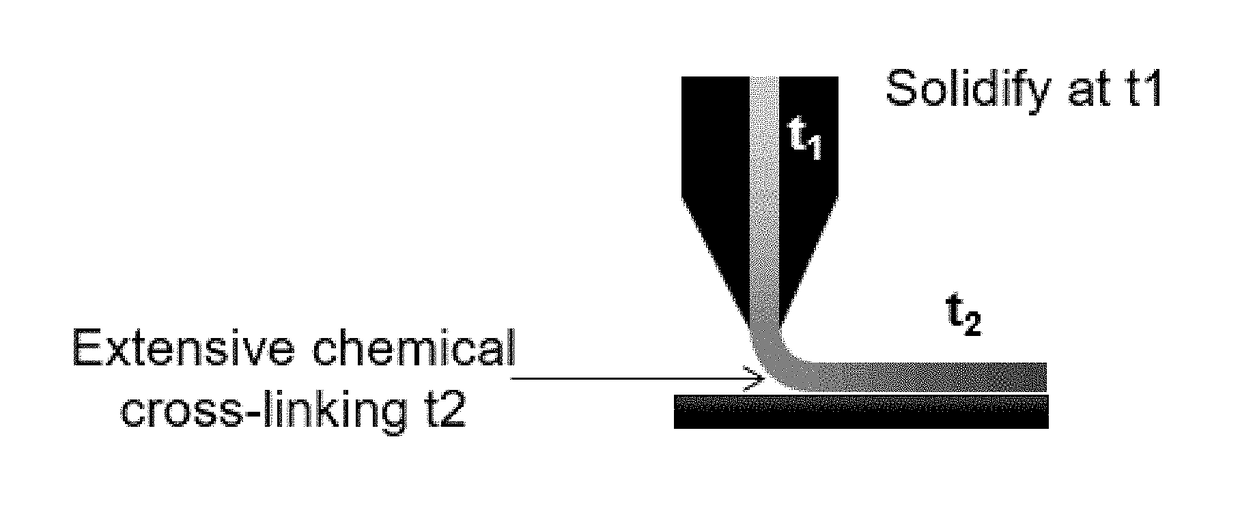
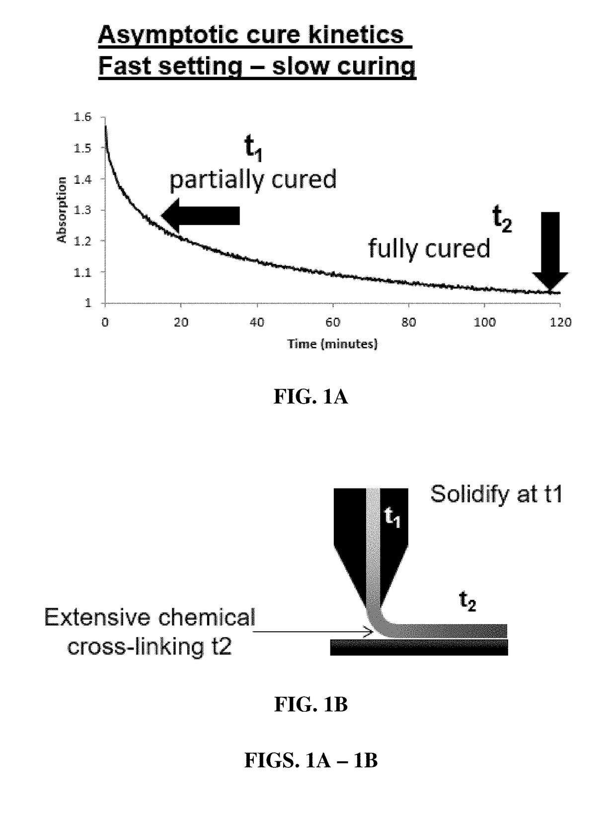
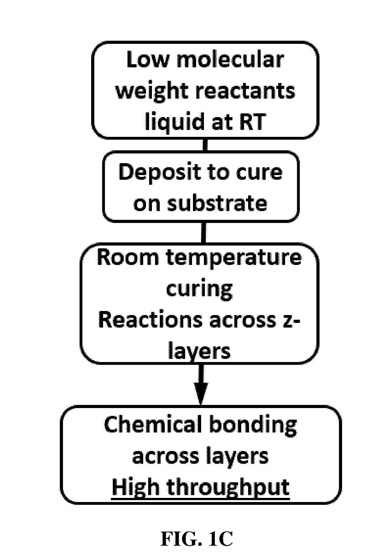
[0010]Thermoset polymers typically outperform thermoplastics in a number of critical areas, including mechanical properties (such as elastic modulus), chemical resistance, thermal stability, and overall durability. Thermosets, like thermoplastics, can also be used in composite structures and can attain higher performance properties when used with structural reinforcements. Polyurea, as used in the present disclosure, may be derived from starting mat

Problems solved by technology

Machining of sintered Nd—Fe—B magnets adds to manufacturing costs and results in significant waste of materials in the form of grinding or cutting swarfs.
Nevertheless, there are some problems being encountered with bonded magnets produced by current processes.
The dilution of the magnetic properties of the magnet powder in non-magnetic media, such as polymer binders, results in low energy (BH)max products.
Moreover, in some applications, manufacturability, mechanical properties, and the ability to withstand corrosive environments,

Method used


Image

  • Bonded permanent magnets produced by additive manufacturing
  • Bonded permanent magnets produced by additive manufacturing
  • Bonded permanent magnets produced by additive manufacturing

Examples


Example

Example 1. Preparation and Analysis of Polyurea-Based Polymer Systems

[0047]Multi-component poly(urea)-based systems for direct print additive manufacturing were determined to be feasible and in some aspects superior to traditional polymer additive manufacturing. The reaction kinetics and transient rheological properties are tunable via slight modifications in chemistry and / or thermal profiles after mixing the amine and isocyanate based components. Four amines and four isocyanates of varying viscosity and reactivity were studied. The identities of the amines and isocyanates and their properties are provided in Tables 1 and 2 below, respectively. The reaction kinetics, flow profile, and printability of various component mixtures and mechanical properties of cast neat and reinforced additively manufactured parts using these amines and isocyanates were studied.

TABLE 1Precursor Amine CompoundsRelativeTradeDesig-Equiv.reactivityNAMEnationWeightViscosity1 = highestNH 1220A229150 cps @ 25° ...

Example

Example 2. Bonded Permanent Magnet Fabrication

[0061]Polymer bonded magnets were produced by extrusion using commercial anisotropic magnet powder (Magnequench™ MQA) mixed with B2, C2, and C4 isocyanate-amine combinations. The initial magnetic properties of the MQA powder was determined with a SQUID magnetometer. The as-received MQA powder has an intrinsic coercivity (Hci) of 12 kOe and a remanence (Mr) of 12.9 kG. The powder was rated for a (BH)max of 38 MGOe. Different vol % (30, 40, 60, and 65) of MQA powders were mixed with C4 isocyanate-amine polymer mixtures using a magnetic stirrer. Unaligned bonded magnet samples were aligned in a field of 9 T overnight. C4 polymers cross-linked and cured while the magnet powders were aligned. Magnetization was measured for each sample at constant applied magnetic field. Similarly, 40 vol % MQA powders were mixed with B2 and C2 isocyanate-amine polymer mixtures and aligned in a magnetic field. Curing times for each of the poly(urea)-NdFeB bond...


PUM

PropertyMeasurementUnit
Magnetic fieldaaaaaaaaaa
Structureaaaaaaaaaa
Viscosityaaaaaaaaaa

Abstract

A method for producing a bonded permanent magnet by additive manufacturing, the method comprising: (i) incorporating components of a reactive precursor material into an additive manufacturing device, the reactive precursor material comprising an amine component, an isocyanate component, and particles having a permanent magnetic composition; and (ii) mixing and extruding the crosslinkable reactive precursor material through a nozzle of the additive manufacturing device and depositing the extrudate onto a substrate under conditions where the extrudate is permitted to cure, to produce a bonded permanent magnet of desired shape. The resulting bonded permanent magnet and articles made thereof are also described.

Description

CROSS REFERENCE TO RELATED APPLICATION[0001]The present application claims benefit of U.S. Provisional Application No. 62 / 453,716, filed on Feb. 2, 2017, all of the contents of which are incorporated herein by reference.STATEMENT REGARDING FEDERALLY SPONSORED RESEARCH[0002]This invention was made with government support under Prime Contract Nos. DE-AC05-00OR22725 and AC02-07CH11358 awarded by the U.S. Department of Energy. The government has certain rights in the invention.FIELD OF THE INVENTION[0003]The present invention relates generally to bonded permanent magnets and methods for producing them. The invention also relates to additive manufacturing methods, such as 3-D printing, fused deposition modeling (FDM), and fused filament fabrication (FFF).BACKGROUND OF THE INVENTION[0004]The growth in compact electronic devices has resulted in the need to develop net-shape high performance permanent magnets with minimal post-fabrication machining. Machining of sintered Nd—Fe—B magnets add...

Claims


Application Information

Patent Timeline
IPC IPC(8): C08G18/08C08G18/34C08G18/32C08G18/73C08G18/75C08G18/76C08G18/78C08K3/08C08K3/04C08K3/34C08K3/36H01F41/02H01F1/057B33Y70/00
CPCC08G2140/00B33Y70/00C08K2201/01C08K2201/011B29K2507/04B29K2505/12B29K2509/08B29K2075/02B29K2105/162B29K2105/18B29K2995/0008B33Y10/00C08G18/346C08G18/0838B29C64/118C08G18/3234C08G18/73C08G18/755C08G18/7621C08G18/7671C08G18/7893C08K3/08C08K3/041C08K3/346C08K3/36H01F41/0253H01F1/0578C08K2003/0856B29C64/106C08G18/792C08G18/3821C08K3/22C08K3/04C08K3/013C08K2003/0843C08K2003/0862C08K2003/085B33Y70/10
Inventor PARANTHAMAN, M. PARANSRIOS, ORLANDOCARTER, WILLIAM G.FENN, DAVIDNLEBEDIM, CAJETAN IKENNA
Owner IOWA STATE UNIV RES FOUND
Why Eureka
Try Eureka